Dual SIM 4G LTE / 3G / 2G / GSM / GPS – Industrial Grade Modem Board ( UART/USB ) – SIM7600EI
Overview
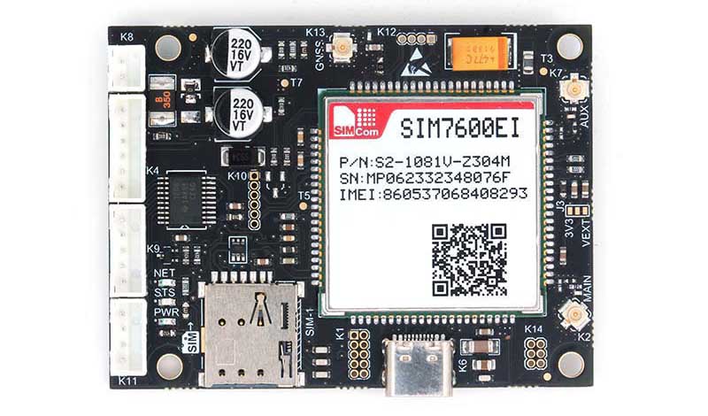
This is a Dual-SIM 4G LTE UART/USB MODEM based on SIM7600EI, which is professionally designed with 4 layer Gold plated PCB having industrial grade protections. It is built with Multi-Band 4G LTE module, SIM7600EI from SIMCOM. As its name implies, it is built with two nano SIM sockets to support Dual SIM (DSSS) Functionalities , one at top side and other at bottom side of the PCB, but both are aligned vertically so as to match the proposed slot on enclosure for easy access.
This MODEM support Dual SIM functionalities as DSSS (Dual SIM Single Standby), which means at a time only One SIM Card is registered to the Network and other SIM card will be disconnected from the network .
Dual SIM Card feature will help us to switch to the other network provider (SIM2), in case of unavailability of first network provider, using AT Commands, without opening the enclosure or turning off the Power.
By default the SIM-1 is enabled and Modem can be used as normal Modem, without any special command or hardware connection
Only, in case of user want to enable the Second SIM , he has to switch the SIM Cards using onboard SIM Switcher IC using SIM7600XX Modules GPIO Pins with the help of AT Commands.
By default the board is populated with Push-Push Nano SIM socket, which can be replaced with normal Push-Pull type SIM Socket as well, on special request. This MODEM is built with support for 4G LTE/3G/2G GSM networks, will automatically rollback to 3G mode in the absence of 4G Network and to 2G mode in the absence of 3G Network, which will enable you to use it across the entire country including remote villages where 4G/3G towers are less populated .
Since this modem supports GNSS, customer can make use of Geo-Location identification using either GPS,GLONASS or BD Satellite networks. This MODEM supports UART communication ( 3V3 & 5V microcontrollers) as well as USB interface with USB Power option. Industrial grade Protections are provided for Noise,Spikes, Anti Static voltages & Surges coming through Power supply, USB, Antenna UFL Connections and through SIM Sockets.
Note: This SIM7600 UART /USB modem support VoLTE , which will enable you to use JIO sim card on it.
Made in INDIA: The Modem is manufactured in fully automatic SMT production line at our own factory in INDIA. It is not a student grade low quality product or low cost china make products available in the market. It is designed in 4 Layer Gold plated PCB and manufactured for industrial and commercial use with maximum protection
Features of the Modem Board
- Support DUAL SIM (DSSS)
- Modem Support UART and USB Communication
- High quality professionally designed Industrial Grade Modem(Made in INDIA)
- 4 Layer Gold Plated PCB for industrial grade performance.
- Built with SIM7600EI Module from SIMCOM
- Works with 4G LTE/ 3G / 2G GSM GPRS Networks
- Automatic Fallback to 3G incase of absence of 4G Network and to 2G incase of absence of 3G Network
- Support GNSS / GPS
- Built in GNSS Geo Location Detection,Protocol: NMEA 0183
- Internet Protocol:TCP/IP/IPV4/IPV6/Multi-PDP/FTP/HTTP/DNS
- Support RNDIS/PPP/ECM ,MQTT/MQTTS ,TLS1.2 ,LBS ,TTS* WIFI Scan
- Firmware update via USB/FOTA*
- SIM7600EI support VoLTE to work with Jio sim
- Onboard 3Nos UFL connector for External 4G LTE Main antenna, Diversity Antenna and GNSS/GPS antenna
- Option to Connect Patch antenna or active antenna for GNSS / GPS
- Onboard 3V3 Voltage regulator for GNSS / GPS external active antenna
- Onboard C-Type USB Connector for USB Communication, Modem Power and module firmware updating
- Dual Nano SIM Card Connector (Push-Push Type) ,one on top and other on bottom of the PCB for easy access.
- Built with microSD card connector on top of the PCB for easy access.
- All important Status , Control and Communication pins are made available at different RMC connectors.
- Option to Turn ON/OFF Modem Power using Host Microcontroller GPIO pins.
- Option to automatically Turn ON Power and Start the modem on powering.
- LM39302 linear LDO voltage regulator is used for providing high-current output.
- Onboard TXB0108 voltage level translator IC which helps to interface with 3V3 & 5V External MicroControllers
- Onboard LED for power indication, Network and status.
- Header option for interfacing ADC,I2c,SPI
- Populated with Transient Voltage Suppressor and Anti Static Protection ICs
- 4 Nos of 3mm Mounting Holes are Provided
- Input voltage : 5V-12V DC / 2Amp
- Working temperature:-40°C ~85°C
What’s On Board
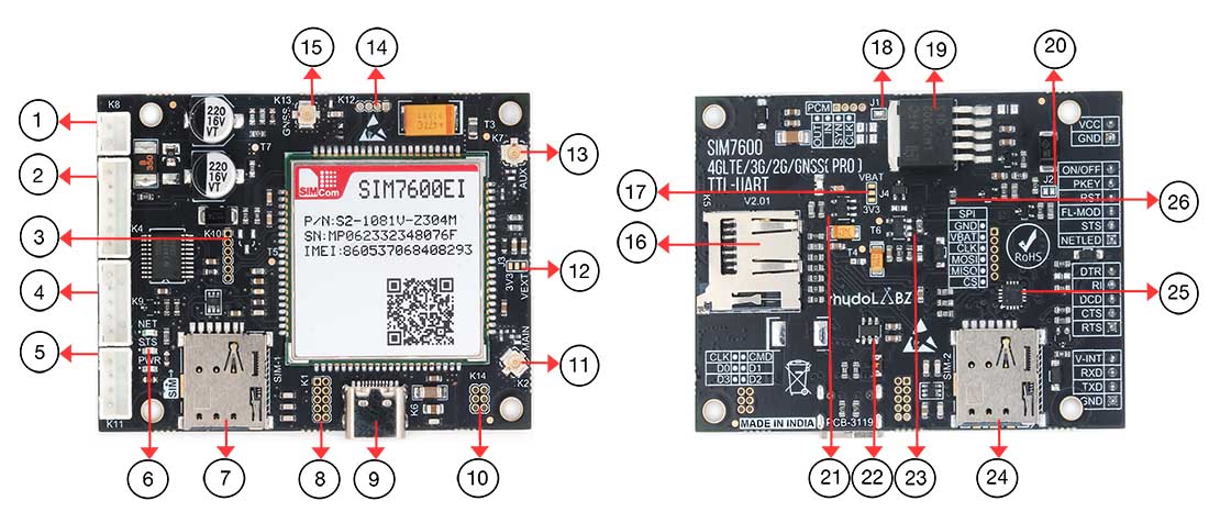
- K8-RMC Connector for Power
- K4-RMC Connector for Control & Status
- K10-SPI Pins
- K9-RMC Connector Serial Hardware Handshaking Pins
- K11- UART Serial
- LED Indicators
- Nano SIM Socket-1
- K1-GPIO/ADC Pins
- USB Type-C Connector for Communication
- K14-SDIO Pins
- K2-Main Antenna
- J3
- K7-Auxiliary/Diversity Antenna
- K12-PCM Audio Interface
- K13-GNSS/GPS Antenna
- K5-Micro SD Card Socket
- J4
- J1
- Regulating IC
- J2
- 3V3 Regulating IC
- USB TVS Diode Protection IC
- Regulating IC
- Nano SIM Socket-2
- SIM Switcher IC
Modem Basic Specifications
| Communication Module * | SIMCOM SIM7600XX |
| Communication Network Supported | 4G LTE, 3G, 2G, GSM, GPRS |
| GNSS (GPS) Support * | Included (External Active Antenna included) * |
| VoLTE Supported | Yes ,Jio Network Supported |
| Power Supply | 5V – 13V DC , USB |
| Current Requirement | 300mA Normally (Peak up to 2Amp) |
| Modem Interfaces | Serial UART (3V3 & 5V) , USB |
| SIM Card | Dual Nano SIM (PUSH-PUSH Type) |
| Normal Operation Temperature | -40°C ~85°C |
| Serial UART Baud rate Supported | From 300bps to 3686400bps ( 115200bps is Default) |
| Firmware Upgrade | Firmware Upgrade Possible Through USB Interface |
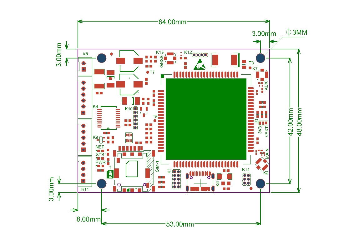
| Dimension | 64mm X 48mm |
Outer Dimension of the Board
Connectors onboard
| Name | Connector Details |
|---|---|
| K1 | ADC,GPIO,I2C Interface Pins* (Without Level Conversion) |
| K2 | UFL Connector for 4G LTE Main Antenna |
| K3 | Nano SIM Socket 1 |
| K4 | Modem Control & Status Interface |
| K5 | Micro SD Card Socket |
| K6 | USB Communication Interface |
| K7 | UFL Connector for Diversity (Aux) Antenna |
| K8 | Power Supply Input |
| K9 | UART Communication Hardware Handshaking Pins for Advanced user |
| K10 | SPI Communications Pins* (Without Level Conversion) |
| K11 | UART Serial Communication Interface |
| K12 | Audio PCM Interface* (Without Level Conversion) |
| K13 | UFL Connector for GPS External Antenna (Active or Passive) * |
| K14 | SDIO Interface* (Without Level Conversion) |
| K15 | Nano SIM Socket 2 |
Connectors mentioned with asterisk * are directly taken out from Module , without any level conversion or Protection . User has to take extra care while using this pins .
PIN Functions
| Pin# | Name | I/O | Function |
|---|---|---|---|
| 1 | VCC | Power | Positive Power Input (5V-12V),DC Voltage |
| 2 | GND | Power | Negative Power Input (Ground) |
| Pin# | Name | I/O | Function |
|---|---|---|---|
| 1 | V-INT | Power | Pin should be provided with required interfacing Voltage level. (Min 2.5V – Max 5V). Suppose user wants to interface modem with external 5V Microcontroller, then this pin should be supplied with 5V, incase of user want to interface with 3.3V Microcontroller , pin must be supplied with 3V3 , so on… |
| 2 | RXD | D.Input | UART Receive input PIN (Voltage level depends on V-INT Pin) |
| 3 | TXD | D.Output | UART Transmit output PIN (Voltage level depends on V-INT Pin) |
| 4 | GND | Power | Ground Return path for communication interface. |
| Pin# | Name | I/O | Function |
|---|---|---|---|
| 1 | ON/OFF | D.Input | This PIN used to turn ON or turn OFF modem power by Disabling EN pin of the internal Voltage Regulator IC. User can select either Automatic Mode or Manual mode powering option by Jumper J3. By default the PCB jumper J3 is Open and the Modem is in Automatic Powering mode. ie. once powered, Modem turned ON itself. If user wants to control the powering of the Modem manually , then the jumper should be Short and to turn ON the modem, user has to pull down ON/OFF input. if unused, keep it Short. |
| 2 | PKEY | D.Input | Used to start and stop the modem by External microcontroller. Modem can start /stop automatically on powering or manually using this pin. A PCB jumper (J4) is provided to select this options. By default this jumper is shorted to start the Modem automatically on powering. User can remove the soldered jumper (J4) and control the modem using this pin. In manual mode, Modem can be started by applying a HIGH level pulse having a width of more than 1 Second on this Pin and later can be stopped by applying again High level pulse having a width of more than 1 Second.if unused, keep it open. |
| 3 | RST | D.Input | Modem can be reset by applying HIGH level pulse having a width of minimum 500 milli second. if unused, keep it open. |
| 4 | FL-Mode | D.Input | Flight Mode Selection Pin ( Input High : Normal Mode and LOW will put the Modem in Flight Mode |
| 5 | STS | D.Output | It is Modem status output, voltage level inverted by a internal transistor and internally pulled up to V-INT voltage level using 10k Resistor. if unused, keep it open. |
| 6 | NET_LED | D.Output | It is GSM Modules NET-LIGHT pin, voltage level inverted by a internal transistor. Indicate network activity status. Collector of this transistor is connected to internal LED (N-LED) and directly shared with this pin to connect external circuitry or LED through a current limiting resistor. if unused, keep it open. |
| Pin# | Name | I/O | Function |
|---|---|---|---|
| 1 | DTR | D.Input | Data terminal ready, sleep mode control pin of the GSM Module , routed after voltage level conversion. Maximum input voltage HIGH level should be same as V-INT pin voltage. if unused, keep it open. |
| 2 | RI | D.Output | Ring indicator Pin of the GSM Module, routed after voltage level conversion. Maximum output voltage HIGH level will be same as V-INT pin voltage. if unused, keep it open. |
| 3 | DCD | D.Output | DCD (Data carrier detection) pin of the GSM Module,routed after voltage level conversion.Maximum output voltage HIGH level will be same as V-INT pin voltage. if unused, keep it open. |
| 4 | CTS | D.Output | CTS (Clear to send ) pin of the GSM Module,routed after voltage level conversion.Maximum output voltage HIGH level will be same as V-INT pin voltage. if unused, keep it open. |
| 5 | RTS | D.Input | RTS (Request to send) pin of the GSM Module,routed after voltage level conversion.Maximum input voltage HIGH level should be same as V-INT pin voltage. if unused, keep it open. |
Jumpers Onboard
| Jumper# | Type | Default | Function |
|---|---|---|---|
| J1 | PCB Jumper | Short | Used to connect and disconnect 3V3 DC Voltage to GPS antenna connectors. For GPS active antenna this jumper should be shorted to turn ON the power supply to LNA built-in and for passive patch antenna it should be kept open (No need of Power). |
| J2 | PCB Jumper | Open | Jumper 3 is used to select manual or automatic power controlling of the modem. By default it is open and in automatic ON Mode,which enable the modem to turn ON instantly upon applying the power to VCC pin. In order to keep Modem OFF while turning ON the power to modem , this jumper should be Shorted. Now the Modem is in Manual ON Mode. Now the Modem will be OFF, until the your micro-controller boots ,starts your application and pulling down the pin ON/OFF of K4 connector. |
| J3 | PCB Jumper | Open | Do Not Change |
| J4 | PCB Jumper | Open | Do Not Change |
| R5 | Resistor | Short | It is used to ground the PKEY pin of the SIM7600XX module permanently, which wil enable automatic starting of the modem on powering. If user would like to control the modem by manually by a host micro-controller via GPIO pin, this Resistor(0R) should be kept open. |
Network Connection Status/Activity LED Indicator
| Name | Logic Level Changes | Status |
|---|---|---|
| PWR (Power) | Always High | Red Power LED will be ON once the MODEM Power Turned ON |
| STS (Status) | Always High | Once modem starts and Ready to communicate this LED will be ON |
| NET(NETLIGHT) | OFF | Power OFF/ Sleep Mode |
| Blink | The Network LED indicates the various status of GSM module like Power on, Network registration & GPRS connectivity. When the modem is powered up, this NETWORK LED will be continuously ON. After the Modem registers in the network (takes between 5-60 seconds), this LED will blink in every seconds. At this stage you can start using Modem for your application,showing that modem is registered with the network. |
Getting Started
Test the Modem out of the box using MODEM USB port (C-Type).
- Insert Nano SIM card to SIM card holder-1 provided on top of the Board. Please ensure the direction of SIM Notch is same as the image shown nearby.
- Connect Provided LTE Antenna to the UFL Connector K2 marked “MAIN” on the modem. #2
- Connect GPS Antenna* to the connector marked K13.
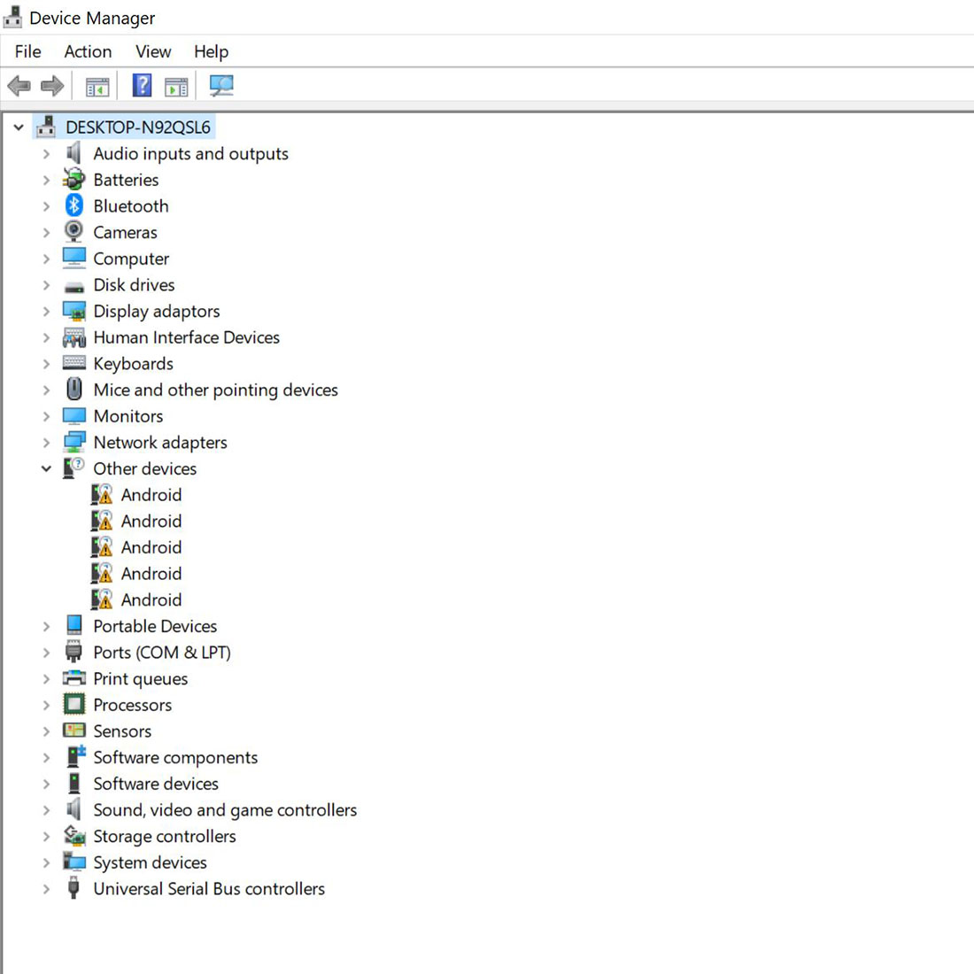
- Install Required SIMCOM USB Driver software from the download link provided.
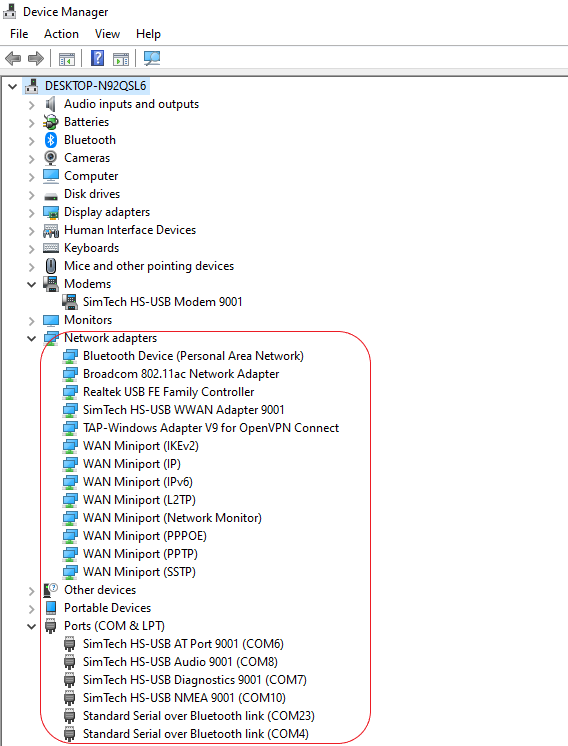
(Device Manager view, before and after installations of USB Driver as below)
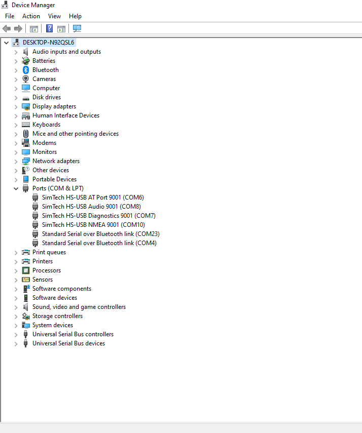
- Connect C-Type USB cable to the modem (K6) and Computer.Normally Modem can be powered from Computer USB Port , If it is not , please provide External Power to K8 by ensuring the Polarity #3
- When the modem is successfully powered-up, the PWR LED (Red) on the modem will be ON, the STS LED(GREEN) will light after 1-2 seconds and the NET LED(BLUE) will blink every second. After the Modem registers in the network (takes between 10-60 seconds), this LED will blink in step of 800 milli seconds.
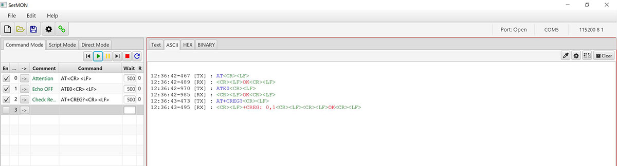
- Open Serial Monitor Software and select respective COM Port (AT Port) and other settings on Computer as below. #4
- Default COM Port Setting are Baud rate :115200, Data bits:8 , Stop bit:1 and Parity:None
- AT<CR><LF>
Now type and send simple attention command, “AT” followed by Carriage Return(“/r”) and New line (“/n”) Character by expecting “OK” from the modem.Some of the Serial Monitor software will automatically append this Carriage Return/New line Character automatically or you have to add it asap.
Once you got “OK” from the modem, all set and we can proceed with other commands…
If you are not getting the “OK” response from the modem , please check whether you are selected proper COM Port, Baud Rate as mentioned above ,Check whether USB cable is properly inserted etc. - ATE0<CR><LF>
To Turn OFF the Echo send by modem , we can issue “ATE0” followed by CR and LF. - AT+CREG?<CR><LF>
Now we can check whether the Modem is registered successfully with the SIM Provider by sending AT+CREG? followed by CR and LF.
If the Reply from the Modem is “+CREG: 0,1” or “+CREG: 0,5” as below , we can confirm that ,the modem is successfully registered to the Network and ready to proceed .
#2: Never use modem without connecting Main Antenna. This may damage the 4G Module.
#3: Since the most of the LAPTOP do not source enough current to power the Modem ,we are not recommending it to power from USB Port
#4: User can use any available Serial Port Software like DOCKLIGHT, REAL TERM, HYPER TERMINAL or QCOM from Quectel (included in the same downloaded Driver zip file)
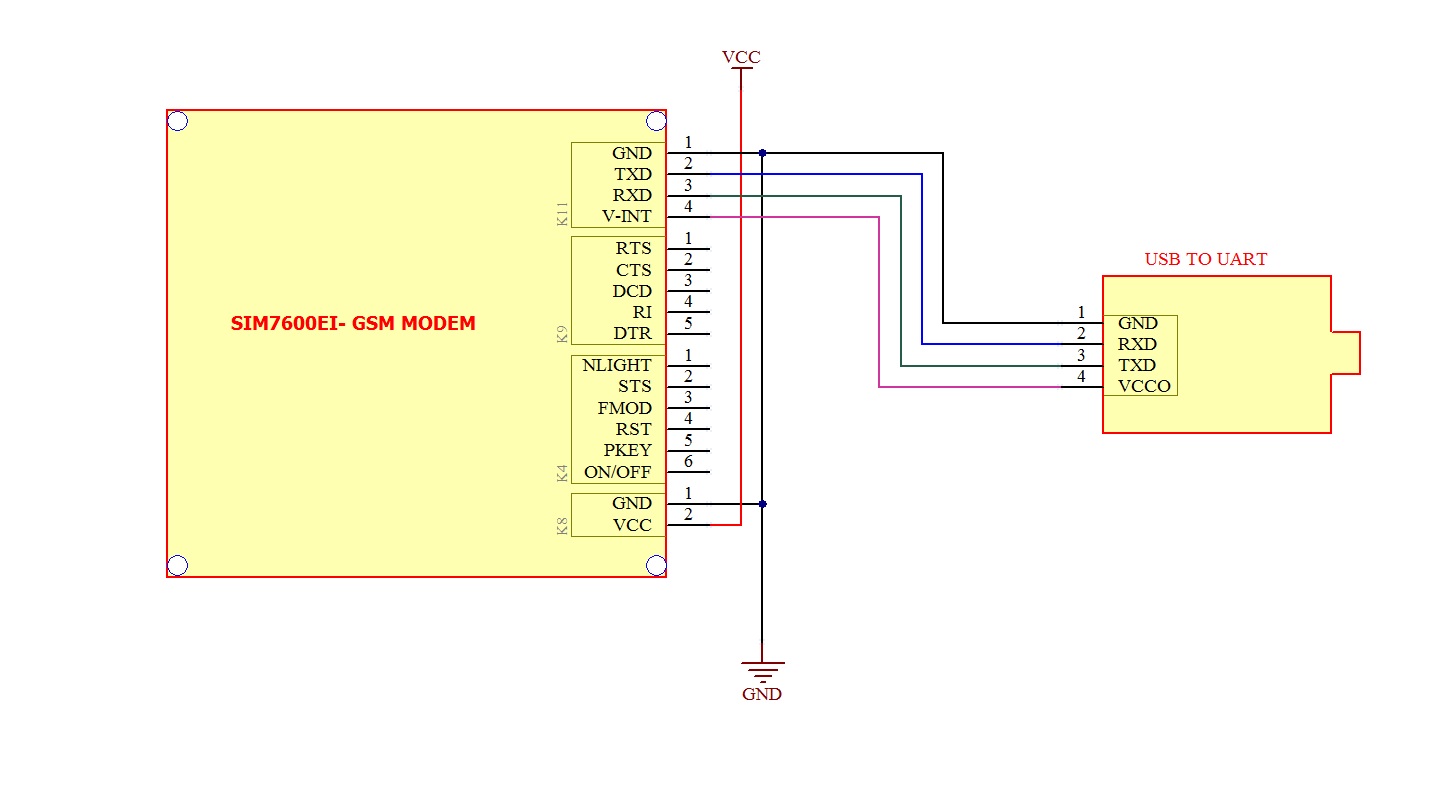
Test the Modem UART using USB to Serial Converter board.
- Insert Nano SIM card to SIM card holder-1 provided on top of the Board. Please ensure the direction of SIM Notch is same as the image shown nearby.
- Connect Provided LTE Antenna to the UFL Connector K2 marked “MAIN” on the modem. #2
- Connect GPS Antenna* to the connector marked K13.
- Connect UART Connector K11 to the USB to Serial Converter board using provided RMC Connector Cable as per below image.
- Connect the USB Converter to the Computer and Install the required USB Driver for the Converter board ( if not installed yet)
- Connect C-Type USB cable to the modem (K6) and Computer to Power the Modem
Normally Modem can be powered from Computer USB Port , If it is not , please provide External Power to K8 , by ensuring the Polarity #3
You may be able to power the modem from USB to Serial Converter board’s VCC Out pin also. But this entirely depends on the Computer’s USB port capability.(Not guaranteed and Recommended)
- When the modem is successfully powered-up, the PWR LED (Red) on the modem will be ON, the STS LED(GREEN) will light after 1-2 seconds and the NET LED(BLUE) will blink every second. After the Modem registers in the network (takes between 10-60 seconds), this LED will blink in step of 800 milli seconds.
- Open Serial Monitor Software and select respective COM Port (AT Port) and other settings on Computer as below. #4
- Default COM Port Setting are Baud rate :115200, Data bits:8 , Stop bit:1 and Parity:None
- AT<CR><LF>
Now type and send simple attention command, “AT” followed by Carriage Return(“/r”) and New line (“/n”) Character by expecting “OK” from the modem.Some of the Serial Monitor software will automatically append this Carriage Return/New line Character automatically or you have to add it asap.
Once you got “OK” from the modem, all set and we can proceed with other commands…
If you are not getting the “OK” response from the modem , please check whether you are selected proper COM Port, Baud Rate as mentioned above ,Check whether USB cable is properly inserted etc. - ATE0<CR><LF>
To Turn OFF the Echo send by modem , we can issue “ATE0” followed by CR and LF. - AT+CREG?<CR><LF>
Now we can check whether the Modem is registered successfully with the SIM Provider by sending AT+CREG? followed by CR and LF.
If the Reply from the Modem is “+CREG: 0,1” or “+CREG: 0,5” as below , we can confirm that ,the modem is successfully registered to the Network and ready to proceed .
#2: Never use modem without connecting Main Antenna. This may damage the 4G Module.
#3: Since the most of the LAPTOP do not source enough current to power the Modem ,we are not recommending it to power from USB Port
#4: User can use any available Serial Port Software like DOCKLIGHT, REAL TERM, HYPER TERMINAL or QCOM from Quectel (included in the same downloaded Driver zip file)
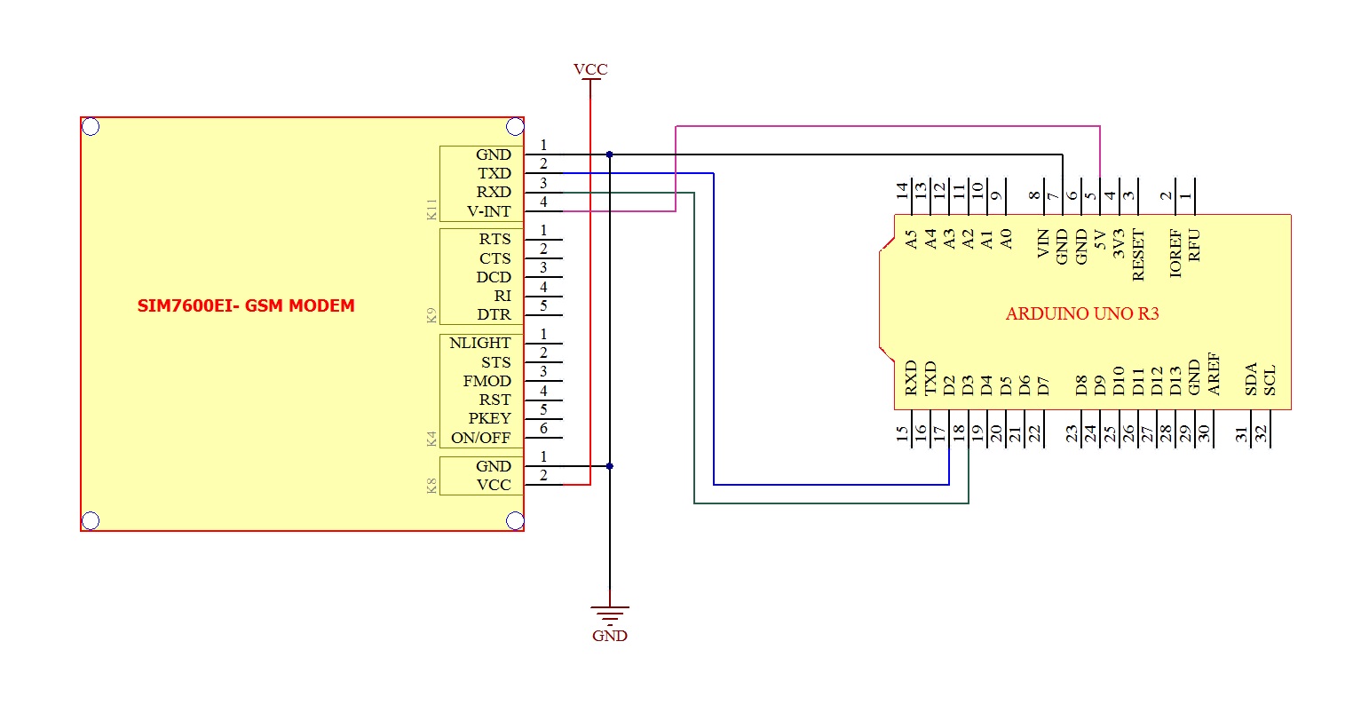
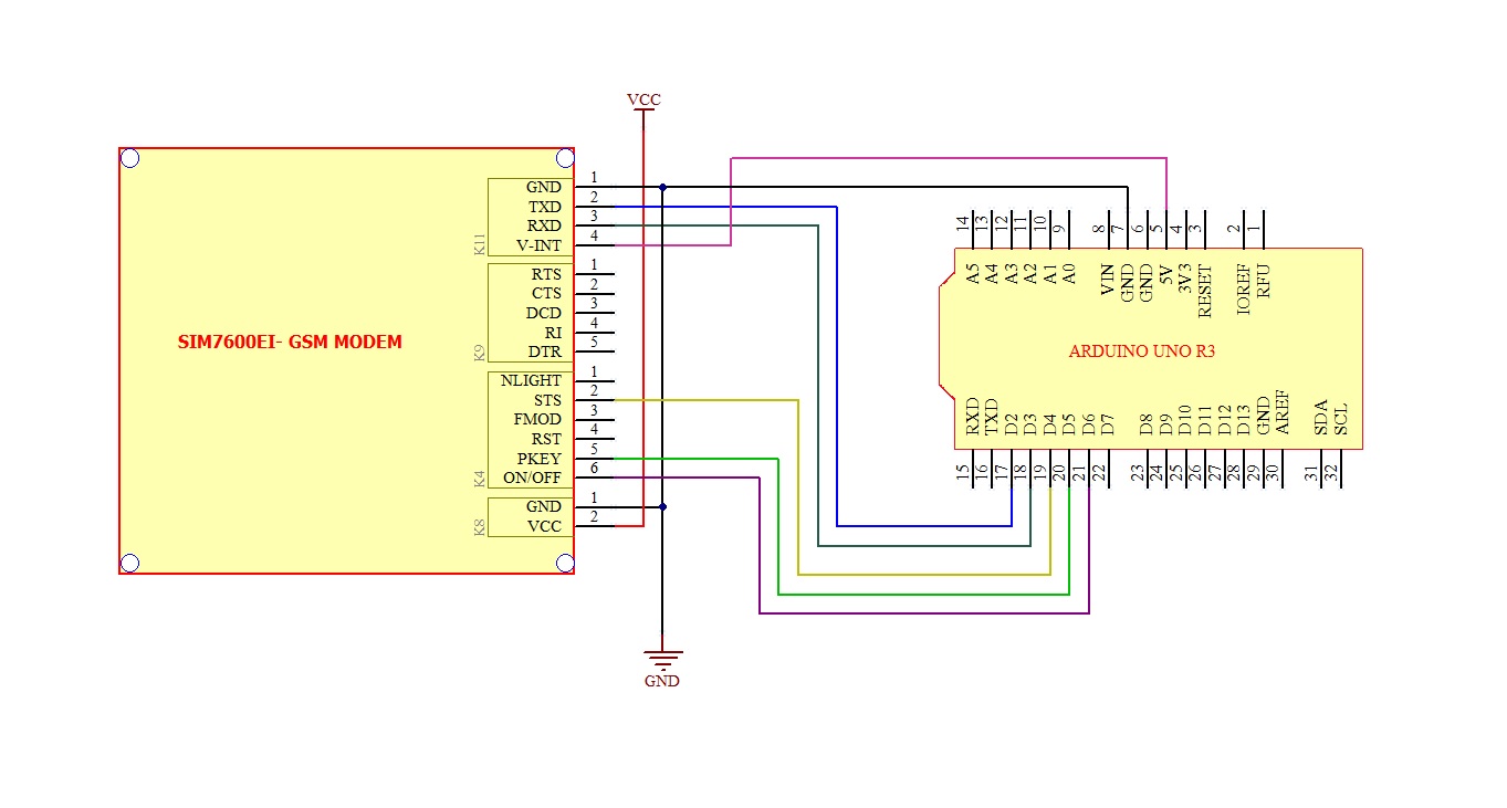
Test the Modem using Arduino UNO Board. (Basic/Simple 4 wire Connection)
- Insert Nano SIM card to SIM card holder-1 provided on top of the Board. Please ensure the direction of SIM Notch is same as the image shown nearby.
- Connect Provided LTE Antenna to the UFL Connector K2 marked “MAIN” on the modem. #2
- Connect GPS Antenna* to the connector marked K13.
- Connect UART Connector K11 to the Arduino board using provided RMC Cable as per below image.
- Connect DC Power supply to the connector K8.(Ensure Polarity).
- You may be able to power the modem from ARDUINO Board VCC pin (5V-12V) also. But this entirely depends on your power supply/Arduino Board Voltage Regulator capability.(Not guaranteed by us)
- When the modem is successfully powered-up, the PWR LED (Red) on the modem will be ON, the STS LED(GREEN) will light after 1-2 seconds and the NET LED(BLUE) will lit continuously till modem getting registered to the network. After the Modem registered to the network (takes between 5-60 seconds), this LED will blink for every seconds.
- Load the sample code provided to Arduino board and check the response on Arduino Serial Port Monitor window.
- Default Setting are Baud rate :115200, Data bits:8 , Stop bit:1 and Parity:None
- Once you got “OK” from the modem, all set and you can proceed with your required commands…
|
1 2 3 4 5 6 7 8 9 10 11 12 13 14 |
void setup() { Serial.begin(115200); // set the baud rate delay(500); Serial.print("AT\r\n"); // Transmit AT to the module delay(500); // wait for a 500ms delay Serial.print("ATE0\r\n"); // Echo Off delay(500); // wait for a 500ms delay } void loop() { while(1); } |
Since Arduino UNO is sharing its Hardware serial port with USB IC via 1K Ohm series resistor , you may face difficulty to run the above code successfully using Default Arduino Hardware serial port along with this modem. If you are facing any such issues , please use Arduino Software Serial port as below .
As per below Code using Software Serial Arduino PIN-2 and PIN-3 are used as RX and TX respectively for interfacing with Modem TX and RX.
|
1 2 3 4 5 6 7 8 9 10 11 12 13 14 15 16 17 18 19 20 |
#include &lt;SoftwareSerial.h&gt;; SoftwareSerial mySerial(2, 3); // Assign pins for RX, TX void setup() { mySerial.begin(115200); // set the baud rate as 115200 } void loop() { mySerial.print("AT\r\n"); // Transmit AT to the module delay(500); // wait for a 500ms delay mySerial.print("ATE0\r\n"); // Echo Off delay(500); // wait for a 500ms delay while(1); // Loop for ever } |
Test the Modem using Arduino UNO Board. (Advanced Mode)
Users those who wishes to control the modem Power, Start/Stop modem manually or check the status of the modem periodically by hardware can opt the this advanced mode circuit connections as below .others can use above simple connection method.
- Remove the Resistor R5 (0R) and keep it open.
- If you want to turn ON/OFF Modem Power by Arduino GPIO, Ensure Jumper J2 shorted, else leave it as it is, need not connect any wires to this Pin “ON/OFF”.
- Insert Nano SIM card to SIM card holder-1 provided on top of the Board. Please ensure the direction of SIM Notch is same as the image shown nearby.
- Connect Provided LTE Antenna to the SMA Connector marked “MAIN” on the modem. #1
- Connect GPS Antenna to the connector marked K13.
- Connect UART Connector K11 to the Arduino board using provided RMC Cable as per below image.
- Connect “Modem Control & Status Interface” Connector K4 to the Arduino board using provided RMC Cable as per below image.
- Connect DC Power supply to the connector K8.(Ensure Polarity).
You may be able to power the modem from ARDUINO Board VCC pin (5V-12V) also. But this entirely depends on your power supply/Arduino Board Voltage Regulator capability.(Not guaranteed by us)
- When the modem is successfully powered-up, the PWR LED (Red) on the modem will be ON, the STS LED(GREEN) will light after 1-2 seconds and the NET LED(BLUE) will lit continuously till modem getting registered to the network. After the Modem registered to the network (takes between 5-60 seconds), this LED will blink for every seconds.
- Load the sample code provided to Arduino board and check the response on Arduino Serial Port Monitor window.
- Default Setting are Baud rate :115200, Data bits:8 , Stop bit:1 and Parity:None
- Once you got “OK” from the modem, all set and you can proceed with your required commands…
|
1 2 3 4 5 6 7 8 9 10 11 12 13 14 15 16 17 18 19 20 21 22 23 24 25 26 27 28 29 30 31 32 33 34 35 36 37 38 39 |
#include <SoftwareSerial.h> SoftwareSerial mySerial(2, 3); // Assign pins for RX, TX #define GSM_PWR_KEY 5 #define GSM_STATUS_PIN 4 #define POWER_ON_OFF_PIN 6 void setup() { digitalWrite(GSM_PWR_KEY,LOW); // ensure the Port Pin low pinMode(GSM_PWR_KEY,OUTPUT); // Pin Setting as output digitalWrite(POWER_ON_OFF_PIN,HIGH); // ensure the Port Pin high in Register pinMode(POWER_ON_OFF_PIN,OUTPUT); // Pin Setting as output pinMode(GSM_STATUS_PIN,INPUT); // Pin Setting as input digitalWrite(POWER_ON_OFF_PIN,LOW); // Power ON the Modem delay(500); digitalWrite(GSM_PWR_KEY,HIGH); // Start the Modem delay(2000); digitalWrite(GSM_PWR_KEY,LOW); while(digitalRead(GSM_STATUS_PIN) != 0) // Wait till modem is ready {} mySerial.begin(115200); // set the baud rate mySerial.print("AT\r\n"); // Transmit AT to the module delay(500); // wait for a 500ms delay mySerial.print("ATE0\r\n"); // Echo Off delay(500); // wait for a 500ms delay } void loop() { //write your codes here while(1); // Loop for ever } |
DUAL SIM (DSSS) Operation
This MODEM support Dual SIM functionalities as DSSS (Dual SIM Single Standby), which means at a time only One SIM Card is registered to the Network and other SIM card will be disconnected from the network .Dual SIM Card feature will help us to switch to the other network provider (SIM2), in case of unavailability of first network provider, using AT Commands, without opening the enclosure or turning off the Power.
Since SIM7600XX is not designed with Dual SIM feature, we have used separate SIM Switcher IC for enabling this feature. By default the SIM1 is enabled and Modem can be used as normal Modem, without any special command.
Only, in case of user want to enable the Second SIM , he has to switch the SIM using onboard SIM Switcher IC using SIM7600XX Modules GPIO Pins with the help of AT Commands.
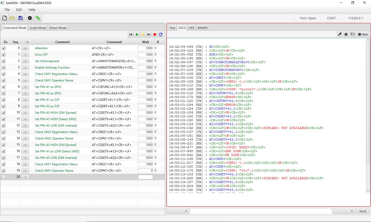
In order to activate Dual SIM (DSSS) Feature, please follow the command sequence below .
- Enable HotSwap Function of the modem (This is a onetime process, Modem will save it automatically)
- AT+UIMHOTSWAPLEVEL=0
- AT+UIMHOTSWAPON=1
- MODEM will use SIM-1 by default which can be verified by.
- AT+CREG? You can verify the Network Registration.
- AT+CSPN? which will show you the operator name of the SIM-1 .
- Set GPIO Pins (Used to Control SIM Switcher IC) as GPIO.
- AT+CGFUNC=41,0 Configure Modules GPIO Pin 41 as GPIO.
- may result in Error if it is already configured as GPIO, just ignore the error
- AT+CGFUNC=43,0 Configure Modules GPIO Pin 43 as GPIO.
- may result in Error if it is already configured as GPIO, just ignore the error
- AT+CGFUNC=41,0 Configure Modules GPIO Pin 41 as GPIO.
- Set Module’s PIN as O/P to control SIM selection IC
- AT+CGRT=43,1
- AT+CGRT=41,1
- In order to Switch to SIM-2
- Simulate SIM Removal by
- AT+CGSETV=43,1
- Select SIM-2 by
- AT+CGSETV=41,1
- Then Simulate SIM Insertion by-
- AT+CGSETV=43,0
- Now SIM-2 will be active with in 5-30 Seconds, which can be tested by –
- AT+CREG? You can verify the Network Registration
- AT+CSPN? which will show you the operator name of SIM-2.
- Simulate SIM Removal by
- In order to Switch back to SIM-1
- Simulate SIM Removal by –
- AT+CGSETV=43,1
- Select SIM1 by
- AT+CGSETV=41,0
- Then Simulate SIM Insertion by-
- AT+CGSETV=43,0
- Now SIM-1 will be active again with in 5-30Seconds, which can be tested by –
- AT+CREG? You can verify the Network Registration .
- AT+CSPN? which will show you the operator name SIM-1 .
- Simulate SIM Removal by –
All above commands should be followed by <CR><LF> ( Carriage Return, Line Feed)
Just Ignore the Error showing for AT Commands ( AT+CGFUNC=41,0 & AT+CGFUNC=43,0). This is because, we are trying to configure these Pins as GPIO , which was already configured as GPIO Mode. It will be better to keep it as it is.
Examples
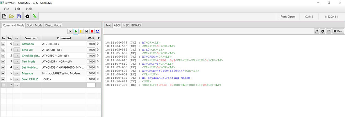
Sending SMS from Computer via USB
- Connect Modem to Computer using either on board USB Port or using External USB to Serial converter board.
- Open Serial port software and enter the below command to send SMS.
- AT
- Attention Command, this signifies that our Modem is working properly.
- Answer Expected : OK
- ATE0
- This Command is being sent to stop the echo.
- Answer Expected : OK
- AT+CREG?
- It is being used to check whether the SIM got registered with the Network.
- Answer Expected : +CREG: 0,1 or +CREG: 0,5
- AT+CMGF=1
- Configuring Text mode for sending SMS
- Answer Expected : OK
- AT+CMGS=”Mobile Number”
- Set the destination mobile number enclosed in the DOUBLE QUOTES.
- Answer Expected : >
- “Hi, How are you?”
- Here we enter our message body followed by character CONTROL-Z (<SUB>)
- Answer Expected : SMS confirmation starting with “+CMGS”
- AT
- SerialMonitor Software Command/Response View for Sending SMS.
Sending SMS using ARDUINO via UART
|
1 2 3 4 5 6 7 8 9 10 11 12 13 14 15 16 17 18 19 20 21 |
void setup() { Serial.begin(115200); // set the baud rate delay(500); Serial.print("AT\r\n"); // Transmit AT to the module delay(500); // wait for a 500ms delay Serial.print("ATE0\r\n"); // Echo Off delay(500); // wait for a 500ms delay Serial.print("AT+CMGF=1\r\n"); // Switch to text mode delay(500); // wait for a 500ms delay } void loop() { Serial.print("AT+CMGS=\"9946670444\"\r\n"); // Send SMS to a cell number delay(500); // wait for a 500ms delay Serial.print("\rTest SMS from rhydoLABZ.com-Cochin\r\n"); // Input SMS Data Serial.write(0x1A); // Ctrl-Z indicates end of SMS delay(500); // wait for a 500ms delay while(1); } |
Since Arduino UNO is sharing its Hardware serial port with USB IC via 1K Ohm series resistor , you may face difficulty to run the above code successfully using Default Arduino Hardware serial port along with this modem. If you are facing any such issues , please use Arduino Software Serial port as below .
As per below Code using Software Serial Arduino PIN-2 and PIN-3 are used as RX and TX respectively for interfacing with Modem TX and RX.
|
1 2 3 4 5 6 7 8 9 10 11 12 13 14 15 16 17 18 19 20 21 22 23 24 25 26 27 28 29 |
#include <SoftwareSerial.h> SoftwareSerial mySerial(2, 3); // Assign pins for RX, TX void setup() { mySerial.begin(115200); // set the baud rate mySerial.print("AT\r\n"); // Transmit AT to the module delay(500); // wait for a 500ms delay mySerial.print("ATE0\r\n"); // Echo Off delay(500); // wait for a 500ms delay mySerial.print("AT+CMGF=1\r\n"); // Switch to text mode delay(500); // wait for a 500ms delay } void loop() { mySerial.print("AT+CMGS=\"9349160503\"\r\n"); // Send SMS to a cell number delay(500); // wait for a 500ms delay mySerial.print("Test MSG"); delay(500); mySerial.write(0X1A); // Ctrl-Z indicates end of SMS delay(500); // wait for a 500ms delay while(1); } |
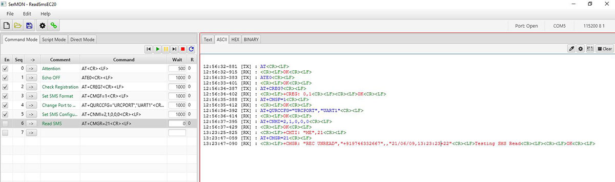
Reading SMS from Computer via USB
- Connect Modem to Computer using either on board USB Port or using External USB to Serial converter board.
- Open Serial port software and enter the below command to read SMS
- AT
- Attention Command, this signifies that our Modem is working properly.
- Answer Expected : OK
- ATE0
- This Command is being sent to stop the echo.
- Answer Expected : OK
- AT+CREG?
- It is being used to check whether the SIM got registered with the Network.
- Answer Expected : +CREG: 0,1 or +CREG: 0,5
- AT+CMGF=1
- Configuring Text mode for SMS
- Answer Expected : OK
- AT+CNMI=2,1,0,0,0
- Configure Modem to notify on incoming SMS reciept. Modem will inform the SMS reciept by “+CMTI: <Message index Number>”
- AT+CMGR=<Message index Number>
- Now Read SMS using <Message index Number> received.
- AT
- SerialMonitor Software Command/Response View for Receiver SMS.
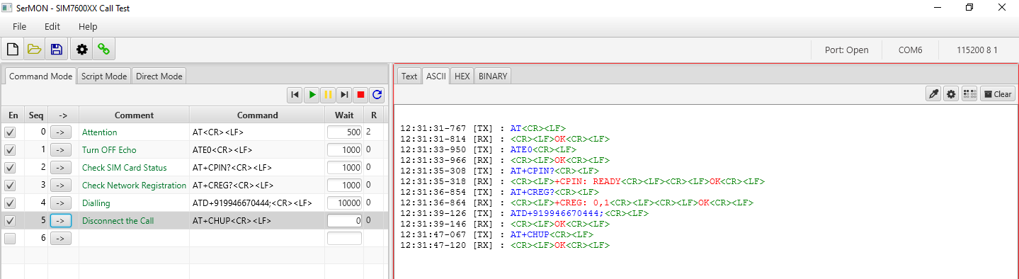
Calling/Dialing from computer.
- Connect Modem to Computer using either on board USB Port or using External USB to Serial converter board.
- Open Serial port software and enter the below command to call
- AT
- Attention Command, this signifies that our Modem is working properly.
- Answer Expected : OK
- ATE0
- This Command is being sent to stop the echo.
- Answer Expected : OK
- AT+CPIN?
- Used to check SIM Card stastus
- Answer Expected : +CPIN: READY, OK
- AT+CREG?
- It is being used to check whether the SIM got registered with the Network.
- Answer Expected : +CREG: 0,1 or +CREG: 0,5
- ATD“Mobile Number”;
- Dialing Command , should end with character Semicolon (“;”)
- Answer Expected : OK, and after few second call will be connected to the number dialed.
- AT+CHUP
- Used to Disconnect the dialed call.
- Answer Expected : OK
- AT
- SerialMonitor Software Command/Response View for voice dialing.
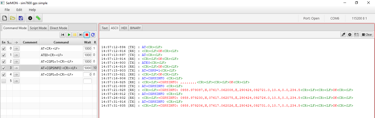
Getting GPS Location (Simple)
- Connect Modem to Computer using either on board USB Port or using External USB to Serial converter board.
- Open Serial port software and enter the below command to get GPS Co-ordinates
- AT
- Attention Command, this signifies that our Modem is working properly.
- Answer Expected : OK
- ATE0
- This Command is being sent to stop the echo.
- Answer Expected : OK
- AT+CGPS=1
- Used to Turn ON GPS
- Answer Expected : OK
- AT+CGPSINFO
- It is being used to Read GPS Coordinates
- Answer Expected : Coordinates
- Kindly note: It may take few seconds to get the proper GPS Data
- AT+CGPS=0
- Used to Turn OFF GPS
- AT
- Serial Monitor Software Command/Response View for GPS Co-ordinates
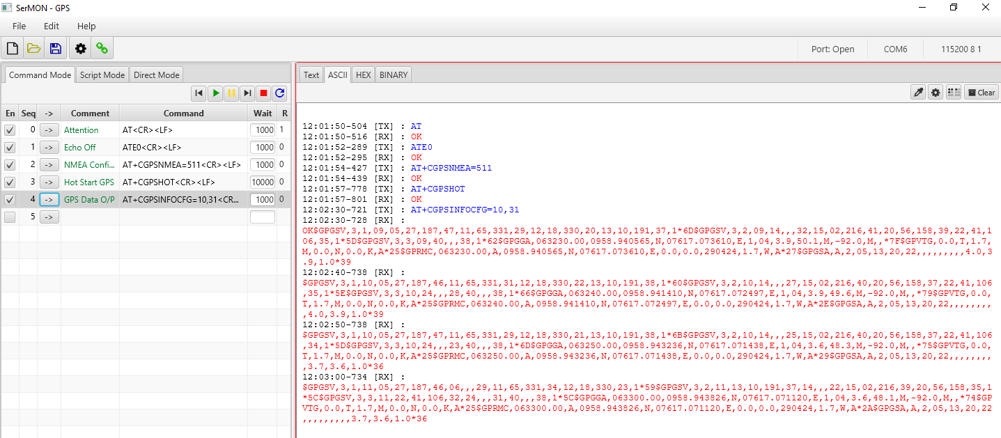
Getting GPS Location (Full NMEA Data)
- Connect Modem to Computer using either on board USB Port or using External USB to Serial converter board.
- Open Serial port software and enter the below command to get GPS NMEA
- AT
- Attention Command, this signifies that our Modem is working properly.
- Answer Expected : OK
- ATE0
- This Command is being sent to stop the echo.
- Answer Expected : OK
- AT+CGPSNMEA=511
- Used to configure NMEA output sentences.
- Answer Expected : OK
- AT+CGPSHOT
- It is being used to start GPS in HOT start mode.
- Answer Expected : OK
- AT+CGPSINFOCFG =10,31
- Used to set the whole NMEA sentence bit(s).
- Answer Expected : OK, Followed by GPS NMEA sentences.
- Kindly note: It may take few seconds to stabilize the GPS Data
- AT
- SerialMonitor Software Command/Response View for GPS Data.
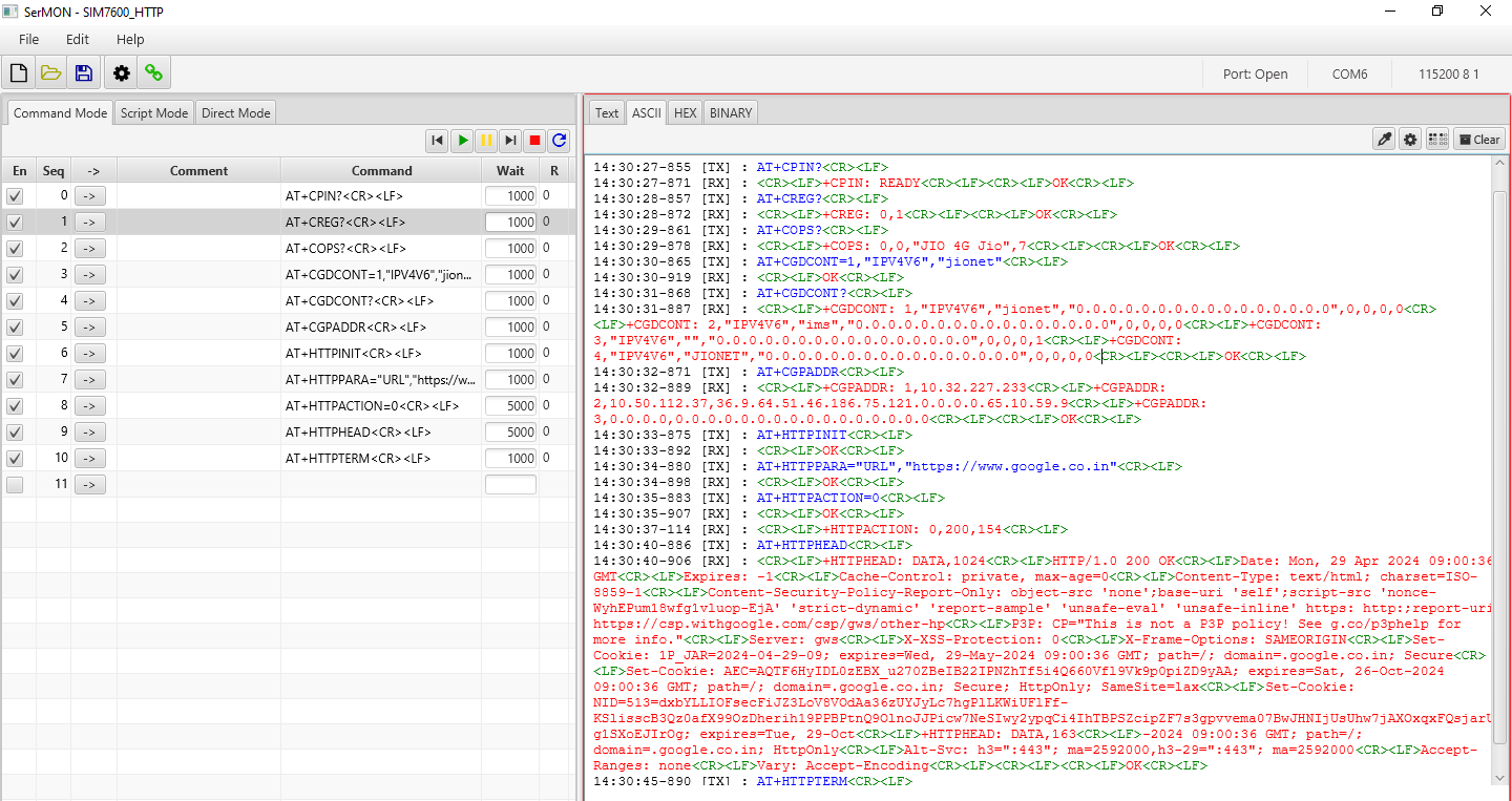
Connecting Internet & Getting Data using HTTP
- Connect Modem to Computer using either on board USB Port or using External USB to Serial converter board.
- Open Serial port software and enter the below command to read website data using HTTP
- AT
- ATE0
- AT+COPS
- AT+CGDCONT=1,”IPV4V6″,”jionet”
- AT+CGDCONT?
- AT+CGPADDR
- AT+HTTPINIT
- Initialize and start the HTTP
- AT+HTTPPARA=”URL”,”https://www.google.co.in”
- Set the URL
- AT+HTTPACTION=0
- Connect the HTTP. (0-get, 1-post, 2-head)
- AT+HTTPHEAD
- Read the response’s header.
- AT+HTTPREAD=0,3
- Read the content (“3” means the number of the reading data)
- AT+HTTPTERM
- Terminate the Http connection
- Serial Monitor Software Command/Response View for Reading Web Data using HTTP.
Surfing Internet using SIM7600 Modem
This SIM7600XX Modem can be used as a wireless networking device to enable the PC or Raspberry PI for surfing the internet by connecting USB.
- Use Type-C USB cable to connect the Modem board and PC.
- You may need to power the modem from external source , if the current from laptop/PC USB is not enough
- Ensure the USB Driver is installed fully and there is no Yellow exclamation marks in Device manager as below
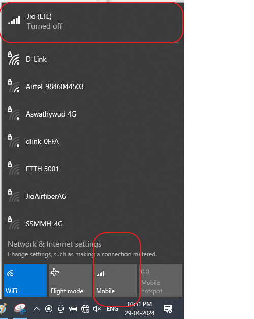
- Clicking on the Network icon near time display will show you either as “Mobile” or “Cellular” with Signal Strength and Network Provider Name [ in this case it is , Jio(LTE) ] appears in the list of available network connections as below.
- Kindly Note: Network Icon will show as Globe (same as no connection), but mobile internet will be there.
- Once you disconnected your WiFi , PC will activate the Internet through 4G Modem automatically.
- In case , you are not getting internet through modem please try by sending this AT command (AT$QCRMCALL=1,1) to the Modem through serial interface port.