Getting started with μOLED displays

Wanna add some glam to your next project?? Then you are at the right place!! We are talking about μOLEDs, the latest trend in embedded sector. They are light, thin and elegant (and really interesting); thats why we wanted to do some sample projects with this beauty ever since we had the first piece of it, and finally we have done one!
Before we start here is a bit of technology behind the μOLEDs. μOLED stands for Micro Organic Light Emitting Diode, a flat light emitting technology that can provide brighter, crisper displays on electronic devices. We have used the 1.30″ display, made of 128×64 individual white OLED pixels, each one is turned on or off by the controller chip. The graphic display panel uses the SH1106 display controller, designed for Common Cathode type OLED panel. The driver chip, SH1106 can communicate in two ways: I2C or SPI. The OLED itself require a 3.3V power supply and 3.3V logic levels for communication but the module boast off 3.3V regulation and level shift features, so you can use these things with 5V devices!.
We tried out both the SPI and I2C communication with the module using an Arduino Uno. It worked fine, well Uno comes handy for anything and everything these days. At first we used a level converter for communication and later we did it without any level conversion, both cases the module worked just fine. First we will have a look at the SPI interface and later on the IIC interface.
SPI Communication with the uOLED display
Caution: Even though the display seems to be 5V tolerant, we do recommend using 3V3 supply & 3V3 level converter while interfacing with 5V controllers.
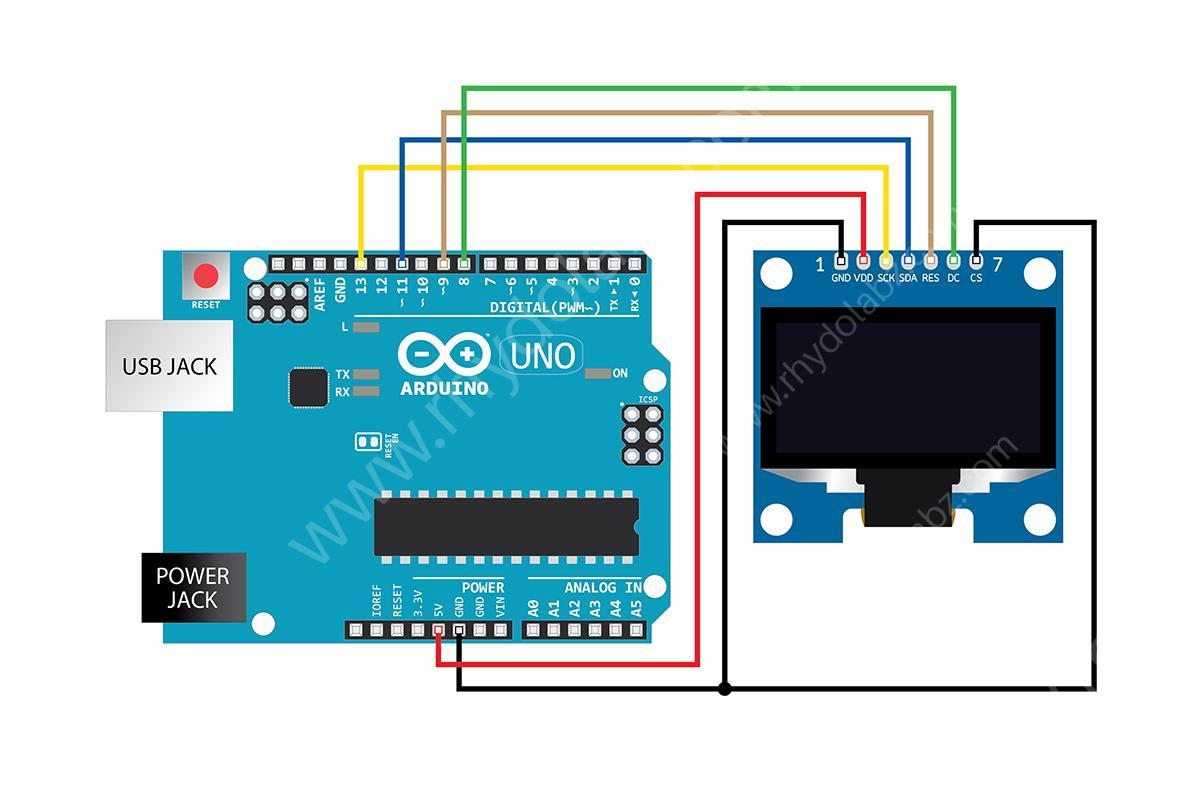
Wire up your connections as shown here and you are ready to go on with the OLED SPI communication. By default the display module is SPI configured and therefore to work with SPI we wont have to mess up the module. The 4 wire serial interface consists of serial clock SCL, serial data MOSI, DC and CS. The OLED also has an additional reset pin (RES). The DC will determine whether the transferred data is written to the display data RAM or command register. You may change pins D/C, Reset and CS to map them to different pins on your Arduino board. Please keep SDA/DI and SCL/CLK connected to your Arduino’s MOSI and SCK (hardware SPI) pins. We used the SPI library that we found on the arduino forum, and here is the code that we used to display our own logo. We can display alphabets, numbers, symbols, images and anything once we learn to handle the pixels.
Sample Code for SPI Communication with the uOLED display
|
1 2 3 4 5 6 7 8 9 10 11 12 13 14 15 16 17 18 19 20 21 22 23 24 25 26 27 28 29 30 31 32 33 34 35 36 37 38 39 40 41 42 43 44 45 46 47 48 49 50 51 52 53 54 55 56 57 58 59 60 61 62 63 64 65 66 67 68 69 70 71 72 73 74 |
#include <SPI.h> #include "SH1106_SPI.h" #define USE_FRAME_BUFFER #ifdef USE_FRAME_BUFFER SH1106_SPI_FB lcd; #else SH1106_SPI lcd; #endif void setup(void) { lcd.begin(); } //------------------------------------------------------------------------------ // File generated by LCD Assistant //------------------------------------------------------------------------------ const unsigned char rhy_128x40 [] = { 0x00, 0x00, 0x00, 0x00, 0x00, 0x00, 0x00, 0x00, 0x00, 0x00, 0x00, 0x00, 0x00, 0x00, 0x00, 0x00, 0x00, 0x00, 0x00, 0x00, 0x00, 0x00, 0x00, 0x00, 0x00, 0x00, 0x00, 0x00, 0x00, 0x00, 0x00, 0x00, 0x00, 0x00, 0x00, 0x00, 0x00, 0x00, 0x00, 0x00, 0x00, 0x00, 0x00, 0x00, 0x00, 0x00, 0x00, 0x00, 0x00, 0x00, 0x00, 0x00, 0x00, 0x00, 0x00, 0x00, 0x00, 0x00, 0x00, 0x00, 0x00, 0x00, 0x00, 0x00, 0x00, 0x00, 0x00, 0x00, 0x00, 0x00, 0x00, 0x00, 0x00, 0x00, 0x00, 0x00, 0x00, 0x00, 0x00, 0x00, 0xC0, 0x00, 0x00, 0x00, 0x00, 0x80, 0x80, 0x00, 0x00, 0x00, 0x00, 0x00, 0x00, 0x00, 0x00, 0x00, 0x00, 0x00, 0x00, 0x00, 0x00, 0x00, 0x00, 0x00, 0x00, 0x00, 0x00, 0x00, 0x00, 0x00, 0x00, 0x00, 0x00, 0x00, 0x00, 0x00, 0x00, 0x00, 0x00, 0x00, 0x00, 0x00, 0x00, 0x00, 0x00, 0x00, 0x00, 0x00, 0x00, 0x00, 0x00, 0x00, 0x00, 0x00, 0x00, 0x00, 0x00, 0x00, 0x00, 0x00, 0xC0, 0xC0, 0x00, 0x00, 0x00, 0x00, 0x00, 0x00, 0x00, 0x00, 0x00, 0x00, 0x00, 0x00, 0x00, 0x00, 0x00, 0x00, 0x00, 0x00, 0x00, 0x00, 0x00, 0x00, 0x00, 0x00, 0x00, 0x00, 0x00, 0x00, 0x00, 0x00, 0x00, 0xE0, 0xE0, 0xE0, 0x00, 0x00, 0x00, 0x00, 0x00, 0x00, 0x00, 0x00, 0x00, 0x00, 0x00, 0x00, 0x00, 0x00, 0x00, 0x00, 0xE0, 0xE0, 0x20, 0x00, 0x00, 0x00, 0x00, 0x00, 0x00, 0x00, 0x00, 0x00, 0x00, 0x00, 0x00, 0x00, 0x00, 0x02, 0xCC, 0x70, 0xCC, 0x01, 0x01, 0x00, 0x00, 0x00, 0x00, 0x00, 0x00, 0x00, 0x00, 0xE0, 0xE0, 0xE0, 0xE0, 0xE0, 0xE0, 0xE0, 0xC0, 0x80, 0x00, 0x00, 0x00, 0xC0, 0xE0, 0xE0, 0xE0, 0xE0, 0xE0, 0xE0, 0xE0, 0xE0, 0x20, 0x00, 0x00, 0x00, 0x00, 0x00, 0x00, 0x00, 0x00, 0x00, 0x00, 0x00, 0x00, 0x00, 0x00, 0x00, 0x00, 0x00, 0xFC, 0xFC, 0x3C, 0x1C, 0x0C, 0x00, 0xFF, 0xFF, 0xFF, 0x3C, 0x0C, 0x0E, 0x0E, 0x3C, 0xFC, 0xF8, 0x00, 0x00, 0xFE, 0xFE, 0xFE, 0x00, 0x00, 0x00, 0x00, 0xFC, 0xFE, 0xFE, 0x00, 0x00, 0xE0, 0xF8, 0xFC, 0x1C, 0x0E, 0x0E, 0x0E, 0x1C, 0x1C, 0xFF, 0xFF, 0xFF, 0x00, 0x80, 0xF0, 0xF8, 0x3C, 0x1C, 0x0E, 0x0E, 0x0E, 0x1C, 0x7C, 0xF8, 0xE0, 0x00, 0x00, 0x00, 0xFF, 0xFF, 0x00, 0x00, 0x00, 0x00, 0x00, 0x00, 0x00, 0x00, 0x00, 0x00, 0x00, 0x80, 0xE0, 0x70, 0x1C, 0x03, 0x00, 0x00, 0x01, 0x07, 0x1C, 0x70, 0xC0, 0x00, 0x00, 0x00, 0x00, 0x00, 0x00, 0xFF, 0xFF, 0xFF, 0x70, 0x70, 0x78, 0xFF, 0xFF, 0xC7, 0x80, 0x00, 0x00, 0x00, 0x00, 0xC0, 0xF8, 0xFE, 0x3F, 0x0F, 0x03, 0x00, 0x00, 0x00, 0x00, 0x00, 0x00, 0x00, 0x00, 0x00, 0x00, 0x00, 0x00, 0x00, 0x00, 0x00, 0x00, 0x00, 0x00, 0x00, 0x7F, 0x7F, 0x00, 0x00, 0x00, 0x00, 0x3F, 0x7F, 0x7F, 0x00, 0x00, 0x00, 0x00, 0x00, 0x7F, 0x7F, 0x00, 0x00, 0x0F, 0x1F, 0x3F, 0x78, 0x70, 0x70, 0x38, 0x7F, 0xFF, 0xFF, 0x00, 0x00, 0x07, 0x1F, 0x3F, 0x38, 0x70, 0x70, 0x70, 0x30, 0x38, 0x1F, 0x3F, 0x3F, 0x00, 0x01, 0x0F, 0x1F, 0x3C, 0x38, 0x70, 0x70, 0x70, 0x38, 0x3E, 0x1F, 0x07, 0x00, 0x00, 0x00, 0x7F, 0x7F, 0x78, 0x70, 0x70, 0x70, 0x70, 0x30, 0x10, 0x00, 0x60, 0x78, 0x7E, 0x67, 0x61, 0x60, 0x60, 0x00, 0x00, 0x00, 0x00, 0x00, 0x60, 0x60, 0x61, 0x7F, 0x7C, 0x70, 0x60, 0x00, 0x00, 0x7F, 0x7F, 0x7F, 0x70, 0x70, 0x78, 0x38, 0x3F, 0x1F, 0x07, 0x40, 0x70, 0x7C, 0x7F, 0x7F, 0x73, 0x70, 0x70, 0x70, 0x30, 0x00, 0x00, 0x00, 0x00, 0x00, 0x00, 0x00, 0x00, 0x00, 0x00, 0x00, 0x00, 0x00, 0x00, 0x00, 0x00, 0x00, 0x00, 0x00, 0x00, 0x00, 0x00, 0x00, 0x00, 0x00, 0x00, 0x00, 0x00, 0x00, 0x00, 0x00, 0x00, 0x00, 0x00, 0x00, 0x00, 0x00, 0x00, 0x00, 0x00, 0x00, 0x00, 0x00, 0x00, 0x00, 0x01, 0x03, 0x00, 0x00, 0x00, 0x00, 0x00, 0x00, 0x00, 0x00, 0x00, 0x00, 0x00, 0x00, 0x00, 0x00, 0x00, 0x00, 0x00, 0x00, 0x00, 0x00, 0x00, 0x00, 0x00, 0x00, 0x00, 0x00, 0x00, 0x00, 0x00, 0x00, 0x00, 0x00, 0x00, 0x00, 0x00, 0x00, 0x00, 0x00, 0x00, 0x00, 0x00, 0x00, 0x00, 0x00, 0x00, 0x00, 0x00, 0x00, 0x00, 0x00, 0x00, 0x00, 0x00, 0x00, 0x00, 0x00, 0x00, 0x00, 0x00, 0x00, 0x00, 0x00, 0x00, 0x00, 0x00, 0x00, 0x00, 0x00, 0x00, 0x00, 0x00, 0x00, 0x00, 0x00, 0x00, 0x00, 0x00, 0x00, 0x00, 0x00, 0x00, 0x00, 0x00, 0x00, 0x00, 0x00, 0x00, 0x00, 0x00, 0x00, 0x00, 0x00, 0x00, 0x00, }; int i; void loop() { lcd.print(F("Loading Bitmap.....")); //oled display lcd.renderAll(); delay(1000); lcd.clear(); // clears the screen and buffer lcd.writeBitmap(rhy_128x40,4,1,128, 5); //drawing bitmap lcd.renderAll(); while(1); } |
Attention! This is important! To display an image make sure that its size falls within the available pixel range (128×64). Only bitmap monochrome images can be crisply displayed as the display can produce either black or white pixels only. Hex data of the image can be obtained using bit map converter, which can then be stored in an array as show in the code above.
IIC Communication with the uOLED display
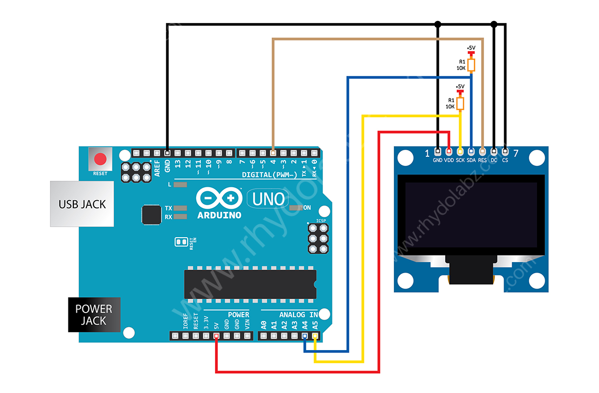
As mentioned before, by default the module is configured for SPI interface. So we will have to change the configuration manually for IIC interface. Well thats simple, desolder the resistor R3, solder it on the vacant R1 slot and short the vacant R8 slot. Thats it and the module is IIC ready. Now, wire up the connection as shown above. For the IIC communication 4pins should connected between the module and the arduino; SCK, SCL, RES and DC.
Sample Code for IIC Communication with the uOLED display
|
1 2 3 4 5 6 7 8 9 10 11 12 13 14 15 16 17 18 19 20 21 22 23 24 25 26 27 28 29 30 31 32 33 34 35 36 37 38 39 40 41 42 43 44 45 46 47 48 49 50 51 52 53 54 55 56 57 58 59 60 61 62 63 64 65 66 |
#include <Arduino.h> #include <Wire.h> #include <MicroLCD.h> LCD_SSD1306 lcd; /* for SSD1306 OLED module */ const PROGMEM uint8_t rhy_128x40 [] = { 0x00, 0x00, 0x00, 0x00, 0x00, 0x00, 0x00, 0x00, 0x00, 0x00, 0x00, 0x00, 0x00, 0x00, 0x00, 0x00, 0x00, 0x00, 0x00, 0x00, 0x00, 0x00, 0x00, 0x00, 0x00, 0x00, 0x00, 0x00, 0x00, 0x00, 0x00, 0x00, 0x00, 0x00, 0x00, 0x00, 0x00, 0x00, 0x00, 0x00, 0x00, 0x00, 0x00, 0x00, 0x00, 0x00, 0x00, 0x00, 0x00, 0x00, 0x00, 0x00, 0x00, 0x00, 0x00, 0x00, 0x00, 0x00, 0x00, 0x00, 0x00, 0x00, 0x00, 0x00, 0x00, 0x00, 0x00, 0x00, 0x00, 0x00, 0x00, 0x00, 0x00, 0x00, 0x00, 0x00, 0x00, 0x00, 0x00, 0x00, 0xC0, 0x00, 0x00, 0x00, 0x00, 0x80, 0x80, 0x00, 0x00, 0x00, 0x00, 0x00, 0x00, 0x00, 0x00, 0x00, 0x00, 0x00, 0x00, 0x00, 0x00, 0x00, 0x00, 0x00, 0x00, 0x00, 0x00, 0x00, 0x00, 0x00, 0x00, 0x00, 0x00, 0x00, 0x00, 0x00, 0x00, 0x00, 0x00, 0x00, 0x00, 0x00, 0x00, 0x00, 0x00, 0x00, 0x00, 0x00, 0x00, 0x00, 0x00, 0x00, 0x00, 0x00, 0x00, 0x00, 0x00, 0x00, 0x00, 0x00, 0xC0, 0xC0, 0x00, 0x00, 0x00, 0x00, 0x00, 0x00, 0x00, 0x00, 0x00, 0x00, 0x00, 0x00, 0x00, 0x00, 0x00, 0x00, 0x00, 0x00, 0x00, 0x00, 0x00, 0x00, 0x00, 0x00, 0x00, 0x00, 0x00, 0x00, 0x00, 0x00, 0x00, 0xE0, 0xE0, 0xE0, 0x00, 0x00, 0x00, 0x00, 0x00, 0x00, 0x00, 0x00, 0x00, 0x00, 0x00, 0x00, 0x00, 0x00, 0x00, 0x00, 0xE0, 0xE0, 0x20, 0x00, 0x00, 0x00, 0x00, 0x00, 0x00, 0x00, 0x00, 0x00, 0x00, 0x00, 0x00, 0x00, 0x00, 0x02, 0xCC, 0x70, 0xCC, 0x01, 0x01, 0x00, 0x00, 0x00, 0x00, 0x00, 0x00, 0x00, 0x00, 0xE0, 0xE0, 0xE0, 0xE0, 0xE0, 0xE0, 0xE0, 0xC0, 0x80, 0x00, 0x00, 0x00, 0xC0, 0xE0, 0xE0, 0xE0, 0xE0, 0xE0, 0xE0, 0xE0, 0xE0, 0x20, 0x00, 0x00, 0x00, 0x00, 0x00, 0x00, 0x00, 0x00, 0x00, 0x00, 0x00, 0x00, 0x00, 0x00, 0x00, 0x00, 0x00, 0xFC, 0xFC, 0x3C, 0x1C, 0x0C, 0x00, 0xFF, 0xFF, 0xFF, 0x3C, 0x0C, 0x0E, 0x0E, 0x3C, 0xFC, 0xF8, 0x00, 0x00, 0xFE, 0xFE, 0xFE, 0x00, 0x00, 0x00, 0x00, 0xFC, 0xFE, 0xFE, 0x00, 0x00, 0xE0, 0xF8, 0xFC, 0x1C, 0x0E, 0x0E, 0x0E, 0x1C, 0x1C, 0xFF, 0xFF, 0xFF, 0x00, 0x80, 0xF0, 0xF8, 0x3C, 0x1C, 0x0E, 0x0E, 0x0E, 0x1C, 0x7C, 0xF8, 0xE0, 0x00, 0x00, 0x00, 0xFF, 0xFF, 0x00, 0x00, 0x00, 0x00, 0x00, 0x00, 0x00, 0x00, 0x00, 0x00, 0x00, 0x80, 0xE0, 0x70, 0x1C, 0x03, 0x00, 0x00, 0x01, 0x07, 0x1C, 0x70, 0xC0, 0x00, 0x00, 0x00, 0x00, 0x00, 0x00, 0xFF, 0xFF, 0xFF, 0x70, 0x70, 0x78, 0xFF, 0xFF, 0xC7, 0x80, 0x00, 0x00, 0x00, 0x00, 0xC0, 0xF8, 0xFE, 0x3F, 0x0F, 0x03, 0x00, 0x00, 0x00, 0x00, 0x00, 0x00, 0x00, 0x00, 0x00, 0x00, 0x00, 0x00, 0x00, 0x00, 0x00, 0x00, 0x00, 0x00, 0x00, 0x7F, 0x7F, 0x00, 0x00, 0x00, 0x00, 0x3F, 0x7F, 0x7F, 0x00, 0x00, 0x00, 0x00, 0x00, 0x7F, 0x7F, 0x00, 0x00, 0x0F, 0x1F, 0x3F, 0x78, 0x70, 0x70, 0x38, 0x7F, 0xFF, 0xFF, 0x00, 0x00, 0x07, 0x1F, 0x3F, 0x38, 0x70, 0x70, 0x70, 0x30, 0x38, 0x1F, 0x3F, 0x3F, 0x00, 0x01, 0x0F, 0x1F, 0x3C, 0x38, 0x70, 0x70, 0x70, 0x38, 0x3E, 0x1F, 0x07, 0x00, 0x00, 0x00, 0x7F, 0x7F, 0x78, 0x70, 0x70, 0x70, 0x70, 0x30, 0x10, 0x00, 0x60, 0x78, 0x7E, 0x67, 0x61, 0x60, 0x60, 0x00, 0x00, 0x00, 0x00, 0x00, 0x60, 0x60, 0x61, 0x7F, 0x7C, 0x70, 0x60, 0x00, 0x00, 0x7F, 0x7F, 0x7F, 0x70, 0x70, 0x78, 0x38, 0x3F, 0x1F, 0x07, 0x40, 0x70, 0x7C, 0x7F, 0x7F, 0x73, 0x70, 0x70, 0x70, 0x30, 0x00, 0x00, 0x00, 0x00, 0x00, 0x00, 0x00, 0x00, 0x00, 0x00, 0x00, 0x00, 0x00, 0x00, 0x00, 0x00, 0x00, 0x00, 0x00, 0x00, 0x00, 0x00, 0x00, 0x00, 0x00, 0x00, 0x00, 0x00, 0x00, 0x00, 0x00, 0x00, 0x00, 0x00, 0x00, 0x00, 0x00, 0x00, 0x00, 0x00, 0x00, 0x00, 0x00, 0x00, 0x00, 0x01, 0x03, 0x00, 0x00, 0x00, 0x00, 0x00, 0x00, 0x00, 0x00, 0x00, 0x00, 0x00, 0x00, 0x00, 0x00, 0x00, 0x00, 0x00, 0x00, 0x00, 0x00, 0x00, 0x00, 0x00, 0x00, 0x00, 0x00, 0x00, 0x00, 0x00, 0x00, 0x00, 0x00, 0x00, 0x00, 0x00, 0x00, 0x00, 0x00, 0x00, 0x00, 0x00, 0x00, 0x00, 0x00, 0x00, 0x00, 0x00, 0x00, 0x00, 0x00, 0x00, 0x00, 0x00, 0x00, 0x00, 0x00, 0x00, 0x00, 0x00, 0x00, 0x00, 0x00, 0x00, 0x00, 0x00, 0x00, 0x00, 0x00, 0x00, 0x00, 0x00, 0x00, 0x00, 0x00, 0x00, 0x00, 0x00, 0x00, 0x00, 0x00, 0x00, 0x00, 0x00, 0x00, 0x00, 0x00, 0x00, 0x00, 0x00, 0x00, 0x00, 0x00, 0x00, 0x00 }; void setup() { lcd.begin(); } void loop() { lcd.clear(); lcd.setCursor(2, 1); // setting cursor position lcd.setFontSize(FONT_SIZE_SMALL); // font size selected is small lcd.println("www.rhydolabz.com"); // display on OLED delay(2000); lcd.clear(); // clears the screen and buffer lcd.setCursor(10, 1); // setting cursor position lcd.draw(rhy_128x40, 128, 40); //drawing bitmap delay(1000); while(1); } |
Converting Graphics to HEX Data
As you have seen, hex data stored in program array was used to display graphics on the display. How do we scale and import a bitmap, then compile it into our Arduino code and send it to the display?? To begin, find a bitmap image that you’d like to print to your OLED. 128×64 monochrome pixels doesn’t give you a lot of room, but you can still get some fun stuff on there. After you’ve picked an image, you’ll need to massage it to make it both monochrome (2-bit color) and the required number of pixels. Most standard image editors can help with this.
The next step is converting that regular image file to an array of char’s. There are a number of programs that can help with this around the web. We recommend LCD Assistant.
To load up an image in LCD Assistant, go to File > Load Image. A preview of the image should open up, make sure it’s the right size. Also make sure the Byte orientation is set to Vertical and the Size endianness is set to Little. The rest of the default settings (8 pixels/byte, etc.) should already be set correctly:
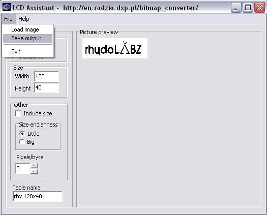
Then go to File > Save output to generate a temporary text file. Open that text file to have a look at your shiny new array. With that array created, copy the entire table over to your Arduino sketch. Fun stuff! Now you can overlay text, or draw on your bitmap. You can even try importing multiple graphics to create animations!
Resources:
- Display Driver Datasheet
- IIC Library For Arduino
- SPI Library For Arduino
- LCD Assistant
- Bitmap2LCD
- TheDotFactory
- Arduino IDE
Shop With Us
Leave a Reply
You must be logged in to post a comment.