How to build a RF Controlled Robot (433MHz)
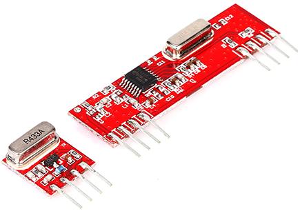 An RF module (radio frequency module) is an electronic device used to transmit and/or receive radio signals between two devices wirelessly. Basically the RF modules communicate each other with the 433 MHz radio signals. When considering RF some terms are most important; module frequency, baud rate, transmitter power, communication distance, antenna length etc.
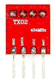
Transmitter module
RF transmitter is an ASK transmitter module capable of transmitting radio wave and modulating it to carry data. Transmitter modules are usually interfaced alongside a microcontroller or an encoder. If you are interfacing with a microcontroller you can use a baud rate of 2400 or 4800. The transmitter Power supply should be in the range of 3 ~ 12V. The specified antenna length is 17cm for 433MHz ISM band.
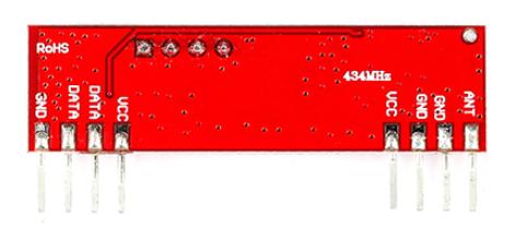
 Receiver module
Superheterodyne RF receiver module receives the modulated RF signal through the antenna. The signal is then demodulated and made available on the data pin of receiver. As in the case of transmitter the power supply of the receiver should be in the range of 3 ~ 12V and the antenna length should be 17cm.
Antenna length calculation
The antenna length can be calculate by the equation:
Wavelength =Velocity of light / Frequency
simply;
length in meters =300 / frequency in MHz
So, for 433MHz; 300/433 =0.69 meters / 4 = 0.17 meters .That’s 1/4 wavelength(Quarter wave) at 433MHz is 17cm.
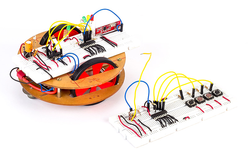
R-bot control using encoder and decoder
In this section we have scribed up on the R-bot control via RF communication. Why RF for rover control?Yeah! Here comes the interesting part, with the RF controlled rover we wont need a micro in the circuit. Then how would it work? Well there comes the cheap encoder-decoder pair handy. Its just pure electronics with no coding. We have used a HT12E-HT12D pair and a Motor Driver; that’s the whole thing.
 HT12E
HT12E
The HT12E is capable of encoding information which consists of N address bits and 12-N data bits. Each address/data input can be set to one of the two logic states. The programmed addresses/data are transmitted together with the header bits via an RF transmission medium upon receipt of a trigger signal(Active low). This cycle will repeat itself as long as the transmission enable (TE) is held low. Once the transmission enable returns high the encoder output completes its final cycle and then stops.
HT12D
HT12D receives data that are transmitted via the encoder, interprets the first N bits of code period as addresses and the last 12–N bits as data, where N is the address code number. A signal on the DIN pin activates the oscillator which in turn decodes the incoming address and data. The decoders will then check the received address three times continuously. If the received address codes all match the contents of the decoder’s local address, the 12–N bits of data are decoded to activate the output pins and the VT pin is set high to indicate a valid transmission. This will last unless the address code is incorrect or no signal is received. The output of the VT pin is high only when the transmission is valid. Otherwise it is always low.
Hardware connections
![]()
power LED glows indicating that everything associated with powering the circuit is working just fine. The input signals, at the transmitter side, are taken through four switches while the outputs are monitored on a set of four LED’s along with R-bot control corresponding to each input switch. The address bits can be left open or pulled low. Here the addresses are pulled low. The encoder converts the parallel address and data into serial which is then transmitted via Dout pin if the trigger is in low state. As we have this pin in its low state the data is continuously transmitted and reaches the data pin of transmitter.
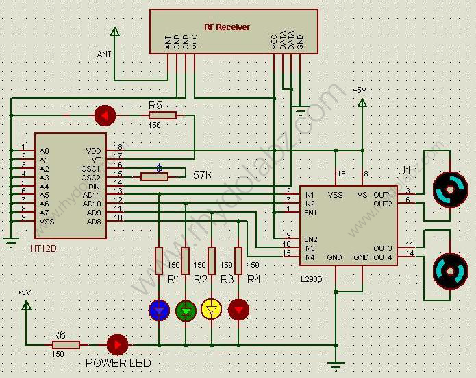
The RF receiver receives the encoded data and it is made available on data pin which is connected to Din pin of the decoder IC. The LED connected in the VT pin of decoder will blink if the received address code matches the decoder’s local address. The decoder converts the received serial data to parallel and then send these decoded signal to L293D Motor driver IC along the D8-D11 pins upon an address match. The forward, backward, left, right movements and clock wise anti clock wise rotations can be done by using the switches. R-bot wheels are connected with 5V DC motor controlled via L293D driver circuit.
We have carried out the same using Dorji’s 500mw High Power ASK Transmitter Module-DRA889TX and High Sensitive ASK Receiver Module-DRA887RX and it worked just fine. The SHUT pin of receiver module should be grounded. If it is high (+5V), the module will go asleep (SHUT- Sleep pin, High effective).
Resources:
Shop with us:
- RF Transmitter and Receiver modules
- Bread board
- Jumper wire pack
- Polymer Lithium Ion Battery – 2200mAh 7.4V
- R-bot
Leave a Reply
You must be logged in to post a comment.