Triple Axis Accelerometer Module-MMA7341 Hookup Guide
Accelerometers are devices that measure acceleration, which is the rate of change of the velocity of an object. They measure in meters per second squared (m/s2) or in G-forces (g). A single G-force for us here on planet Earth is equivalent to 9.8 m/s2, but this does vary slightly with elevation (and will be a different value on different planets due to variations in gravitational pull). Accelerometers are useful for sensing vibrations in systems or for orientation applications. Accelerometers can measure acceleration on one, two, or three axis. 3-axis units are becoming more common as the cost of development for them decreases.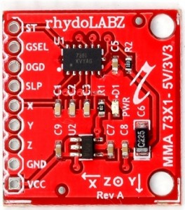
Rhydolabz’s Triple Axis Accelerometer Module-MMA7341 Accelerometer module is based on the popular Freescale MMA7341 three-axis analog accelerometer IC, which reads off the X, Y and Z acceleration as analog voltages. By measuring the amount of acceleration due to gravity, an accelerometer can figure out the angle it is tilted at with respect to the earth. By sensing the amount of dynamic acceleration, the accelerometer can find out how fast and in what direction the device is moving. Using these two properties, you can make all sorts of cool projects, from musical instruments (imagine playing and having the tilt connected to the distortion level or the pitch-bend) to a velocity monitor on your car (or your children’s car). The accelerometer is very easy interface to an Arduino Micro-controller using 3 analog input pins, and can be used with most other micro controllers, such as the PIC or AVR.
Accelerometers with an analog interface show accelerations through varying voltage levels. These values generally fluctuate between ground and the supply voltage level. An ADC on a microcontroller can then be used to read this value. 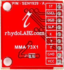
For most accelerometers, the basic connections required for operation are power and the communication lines.This is a Tri axis accelerometer board with on-board low dropout linear voltage regulator and all required components as per data-sheet. The sensor requires a very low amount of power and has a g-select input which switches the accelerometer between ±3g and ±11g measurement ranges. Other features include a sleep mode, signal conditioning, a 1-pole low pass filter, temperature compensation, self test, and 0g-detect which detects linear free-fall. Zero-g offset and sensitivity are factory set and require no external devices.
This breadboard friendly board breaks out every pin of the MMA7341L to a 9-pin, 0.1″ pitch header. The sensor works on power between 3.3V to 6VDC, yes offcourse 5V is inbetween !!. This wide power supply range helps you to use this module with ARM (3V3) based product as well as 5V Arduinos and PICs. All three axis have their own analog output with onboard low pass filter.
Module Features:![]()
- Two selectable measuring ranges (±3g, ±11g)
- Tri Axis (X,Y,Z) Analog output
- Onboard power LED
- Onboard LDO Voltage Regulator
- Onboard Signal conditioning with low pass filter
- Breadboard friendly – 0.1″ pitch header
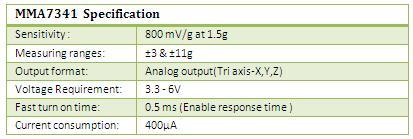
- Low current consumption: 400 µA
- Sleep mode: 3 µA
- Low voltage operation: 3.3 V – 6 V
- High sensitivity (800 mV/g at 1.5g)
- Fast turn on time (0.5 ms enable response time)
- Self test for freefall detect diagnosis
- 0g-Detect for freefall protection
- Robust design, high shocks survivability
- Dimensions: 1″x 1″
Specifications:![]()
![]()
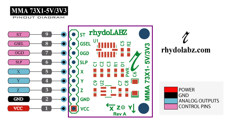 PIN details of Triple Axis Accelerometer Module-MMA7341 is as shown below
 Layout:
![]()
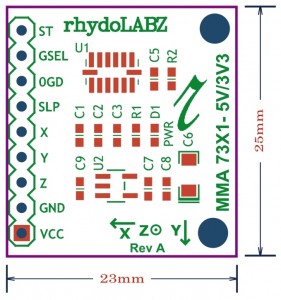
Note:-
Input voltage range (VCC) = 3.3V- 6V
All other pins are @ 3V only
Components details:![]()
- The capacitors used in Triple Axis Accelerometer Module-MMA7341 are given below.
- C1,C2,C3 – Use 3.3nF capacitor on the outputs of the accelerometer to minimize clock noise (from the switched capacitor filter circuit)
- C5 – Use 0.1 µF capacitor on VDD to decouple the power source
- C6 – Cout for LP2985 voltage regulator. Minimum capacitor value (2.2µf) for stability (can be increased without limit for improved stability and transient response)
- C7 & C8 – BYPASS capacitors for low-noise operation with values 10nF and 0.1 µF respectively.
- C9 – Use 0.1 µF capacitor on VCC to decouple the power source
- Jumper J1 – By shorting J1 we can bypass on board regulator IC LP2985 ,its optional. In Rhydolabz’s MMA7341 board j1 is not connected.The input voltage range is 3.3V- 6V and MMA7341 IC needed only 3v, so we use voltage regulator circuit to convert 3.3V- 6V range to 3V.
- LED D1 – A red led is used for power indication.
- The resistors used in Triple Axis Accelerometer Module-MMA7341 are given below
- R1 – Pull up resistor R1 is connected to D1.
- R2 – Pull up resistor R2 is connected to SLP pin of MMA7341,which is an active low pin.
1. Testing Triple Axis Accelerometer Module-MMA7341 using Arduino
Here is the guide illustrates how to connect an Arduino to the MMA7341 Triple Axis Accelerometer. The following is a table describing which pins on the Arduino should be connected to the pins on the accelerometer:
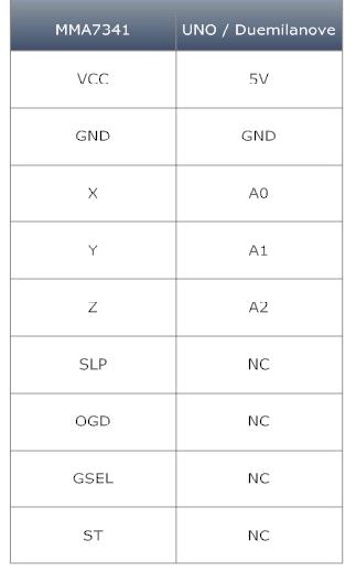
Note:-NC stands for No Connection
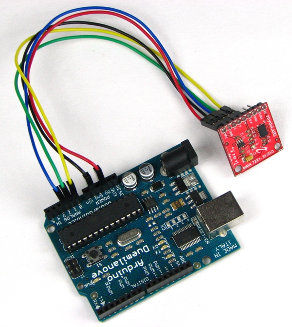
Connect Triple Axis Accelerometer MMA7341 with Arduino as shown below.
|
1 2 3 4 5 6 7 8 9 10 11 12 13 14 15 16 17 18 19 20 21 22 23 24 25 26 27 28 29 30 31 32 33 34 35 36 |
int x; // x axis variable int y; // y axis variable int z; // z axis variable /*************************************************************************************** Function : setup() Description : Use it to initialize variables, pin modes, start using libraries, etc. The setup function will only run once, after each power up or reset of the Arduino board. ***************************************************************************************/ void setup() { Serial.begin(9600); // opens serial port, sets data rate to 9600 bps } /*************************************************************************************** Function : loop() Description : Loops consecutively, allowing your program to change and respond. Use it to actively control the Arduino board. ***************************************************************************************/ void loop() { x = analogRead(0); // read the 0th analog input pin y = analogRead(1); // read the first analog input pin z = analogRead(2); // read the second analog input pin Serial.print("X = "); // print x adc value Serial.println(x); Serial.print("Y = "); // print y adc value Serial.println(y); Serial.print("Z = "); // print z adc value Serial.println(z); delay(100); } |
Connect MMA7341 module with Arduino and upload the Arduino example code. Then open the serial monitor, MMA7341 will output the acceleration values on x, y and z axis as shown below.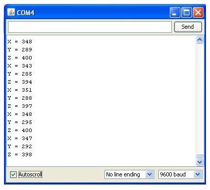
2. Testing Triple Axis Accelerometer Module-MMA7341 using PIC16F877A
When interfacing Triple Axis Accelerometer Module-MMA7341 with PIC16F877A micro-controller, The X,Y,Z pins of the sensor is connected to Port A of the micro-controller. Here X,Y,Z pins are connected to RA2, RA1, RA0 respectively. Connection diagram is shown below.
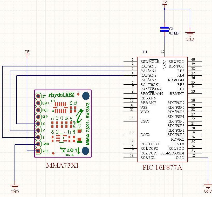 Testing Triple Axis Accelerometer Module-MMA7341 with PIC16F877A, sample program is shown below. Using this program we are reading output from X,Y and Z axis during vibration.
|
1 2 3 4 5 6 7 8 9 10 11 12 13 14 15 16 17 18 19 20 21 22 23 24 25 26 27 28 29 30 31 32 33 34 35 36 37 38 39 40 41 42 43 44 45 46 47 48 49 50 51 52 53 54 55 56 57 58 59 60 61 62 63 64 65 66 67 68 69 70 71 72 73 74 75 76 77 78 79 80 81 82 83 84 85 86 87 88 89 90 91 92 93 94 95 96 97 98 99 100 101 102 103 104 105 106 107 108 109 110 111 112 113 114 115 116 117 118 119 120 121 122 123 124 125 126 127 128 129 130 131 132 133 134 135 136 137 138 139 140 141 |
/********************************************************************************** * Microcontroller -- PIC 16 F877 - 40-pin - 8-bit * * Clock Frequency is 20 MHz -- Period in 200 Nano Seconds * * USART - BaudRate 9600 * * This program is used to read MEMS accelermeter **********************************************************************************/ #include<pic.h> #include"delay.c" int X_Value=0; int Y_Value=0; int Z_Value=0; void ADC_init() ; void send(char); int adc_conv(int); void SerialPortInit() ; void SendData(char); void display(int value ); void MSdelay(unsigned int); static void Send2USART(const char *CPtr1); void main() { TRISC=0X80; TRISE=0X07; SerialPortInit() ; ADC_init(); while(1) { Send2USART("X-axis:"); X_Value=adc_conv(2); // select channel 2 for reading X axis display(X_Value ); SendData(' '); Send2USART("Y-axis:"); Y_Value=adc_conv(1); // select channel 1 for reading Y axis display(Y_Value ); SendData(' '); Send2USART("Z-axis:"); Z_Value=adc_conv(0); // select channel 0 for reading Z axis display(Z_Value ); SendData('\n'); SendData('\r'); } } /******************************************************************************* * Function : Send2USART * Description : Group of data send serially ******************************************************************************/ static void Send2USART(const char *Cptr1) { while(*Cptr1 != '\0') { SendData(*Cptr1); Cptr1++; } } /******************************************************************************* * Function : display * Description : Display adc value function ******************************************************************************/ void display(int value ) { char k=1; char array[4]; for(k=1;k<=4;k++) { array[k]=value%10; value=value/10; } for(k=4;k>=1;k--) { SendData(array[k]+'0'); } } /******************************************************************************* * Function : SerialPortInit * Description : Usart Initialization function - Baud Rate 9600 ******************************************************************************/ void SerialPortInit() { GIE=1; SYNC=0; TXEN=1; BRGH=1; SPEN=1; CREN=1; PEIE=1; RCIE=1; SPBRG=129; } /******************************************************************************* * Function : ADC_init * Description : Adc Initialization function ******************************************************************************/ void ADC_init() { ADFM=1; PCFG3=0; PCFG2=0; PCFG1=0; PCFG0=0; } /******************************************************************************* * Function : adc_conv * Description : Adc Conversion function ******************************************************************************/ int adc_conv(int channel) { int ab; ADCON0=0x81|channel<<3; //channel selection DelayMs(1); ADGO=1; //start AD conversion while(ADGO!=0); //wiating for competion of AD conversion ab=ADRESH; //assign 2bit value ADRSH register to variable ab ab=ADRESH<<8; //8 times shift variable ab value ab=ab|ADRESL; //combine ADRESL & ab value return(ab); } /******************************************************************************* * Function : SendData * Description : Send a data serially ******************************************************************************/ void SendData(char sdata) { TXREG=sdata; while(TRMT!=1); } /******************************************************************************* * Function : MSdelay * Description : Generate 1ms delay ******************************************************************************/ void MSdelay(unsigned int val) { unsigned int del,del1; for(del=1;del<=val;del++) { for(del1=0;del1<=331;del1++); } } |
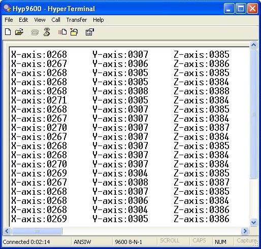
When PIC16F877A micro-controller receives Triple Axis Accelerometer Module-MMA7341 datas and are displayed on serial monitor as shown below.
Resources![]() Schematic
Schematic
MMA7341L Data Sheet
How to Buy:![]() Click here to buy RhydoLABZ’s Triple Axis Accelerometer Module-MMA7341
Click here to buy RhydoLABZ’s Triple Axis Accelerometer Module-MMA7341
Support:![]() Please share your ideas with us, visit our forum for discussion
Please share your ideas with us, visit our forum for discussion
Frequently Asked Questions(FAQ):![]() Q.What is an accelerometer ?
Q.What is an accelerometer ?
Ans: An accelerometer is an electro-mechanical device that will measure acceleration forces. These forces may be static, like the constant force of gravity pulling at your feet, or they could be dynamic – caused by moving or vibrating the accelerometer.
Q.What is range of an accelerometer?
Ans: Range is the level of acceleration supported by the sensor’s output signal specifications, typically specified in ±g. This is the greatest amount of acceleration the part can measure and accurately represent as an output. For example, the output of a ±3g accelerometer is linear with acceleration up to ±3g. If it is accelerated at 4g, the output may rail.
Q. why you are getting data even while the accelerometer is at rest?
Ans:The reading of the accelerometer when at rest is due to the zero g output (typically 2.5V, varies depending upon the accelerometer model you have). Consider a sensor in a steady state on a horizontal surface, will measure 0g in X axis and 0g in Y axis whereas the Z axis will measure 1g, this Z axis value is getting at output of the accelerometer.
Q.What is zero-g offset?
Ans: Zero-g level Offset (Off) describes the deviation of an actual output signal from the ideal output signal if there is no acceleration present. A sensor in a steady state on a horizontal surface will measure 0g in X axis and 0g in Y axis whereas the Z axis will measure 1g
Q.Where would you use an accelerometer?
Ans:There are a number of practical applications for accelerometers; accelerometers are used to measure static acceleration (gravity), tilt of an object, dynamic acceleration, shock to an object, velocity, orientation and the vibration of an object. Cell phones, computers and washing machines now contain accelerometers. Other practical applications include: Measuring the performance of an automobile, measuring the vibration of a machine, measuring the motions of a bridge, measuring how a package has been handled .

Leave a Reply
You must be logged in to post a comment.