3 Axis Accelerometer with Regulator – ADXL335
This Accelerometer module is based on the popular ADXL335 three-axis analog accelerometer IC, which reads off the X, Y and Z acceleration as analog voltages. By measuring the amount of acceleration due to gravity, an accelerometer can figure out the angle it is tilted at with respect to the earth. By sensing the amount of dynamic acceleration, the accelerometer can find out how fast and in what direction the device is moving. Using these two properties, you can make all sorts of cool projects, from musical instruments (imagine playing and having the tilt connected to the distortion level or the pitch-bend) to a velocity monitor on your car (or your children’s car). The accelerometer is very easy interface to an Arduino Micro-controller using 3 analog input pins, and can be used with most other micro controllers, such as the PIC or AVR.
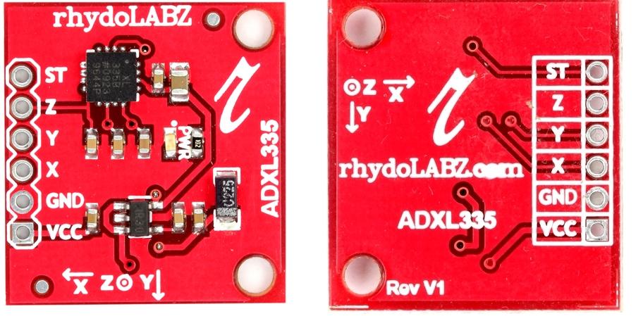 For most accelerometers, the basic connections required for operation are power and the communication lines. Accelerometers with an analog interface show accelerations through varying voltage levels. These values generally fluctuate between ground and the supply voltage level. An ADC on a microcontroller can then be used to read this value. These are generally less expensive than digital accelerometers.
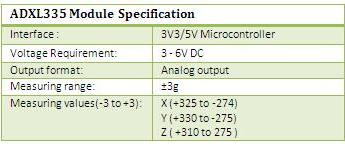
ADXL335 is 3 axis accelerometer with on board voltage regulator IC and signal conditioned Analog voltage output. The module is made up of ADXL335 from Analog Devices. The product measures acceleration with a minimum full-scale range of ±3 g. It can measure the static acceleration of gravity in tilt-sensing applications, as well as dynamic acceleration resulting from motion, shock, or vibration.
The user selects the bandwidth of the accelerometer using the CX, CY, and CZ capacitors at the XOUT, YOUT, and ZOUT pins. Bandwidths can be selected to suit the application, with a range of 0.5 Hz to 1600 Hz for the X and Y axis, and a range of 0.5 Hz to 550 Hz for the Z axis.This is the latest in a long, proven line of analog sensors – the holy grail of accelerometers. Accelerometers are generally low-power devices. The required current typically falls in the micro (µ) or milli-amp range The ADXL335 is a triple axis accelerometer with extremely low noise and power consumption – only 320uA! The sensor has a full sensing range of +/-3g.
There is an on-board voltage regulation, which enable you to power the board with 3V to 6V DC. Board comes fully assembled and tested with external components installed. The included 0.1uF capacitors set the bandwidth of each axis to 50Hz.
Features:![]()
- 3V-6V DC Supply Voltage
- Onboard LDO Voltage regulator
- Can be interface with 3V3 or 5V Microcontroller.
- All necessary Components are populated.
- Ultra Low Power: 40uA in measurement mode, 0.1uA in standby@ 2.5V
- Tap/Double Tap Detection
- Free-Fall Detection
- Analog output
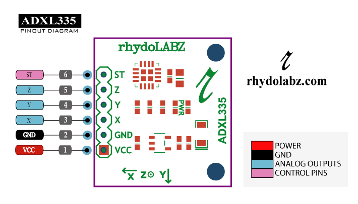
 PIN diagram:
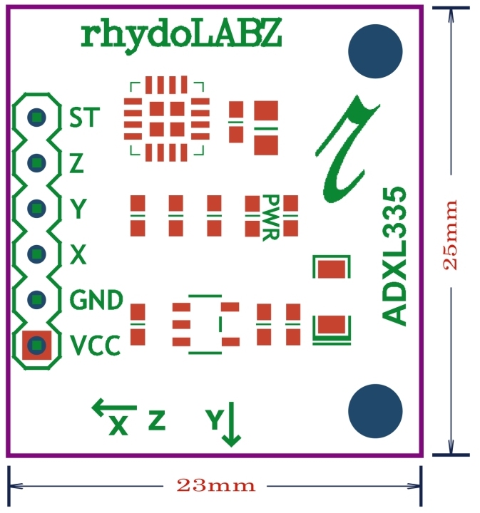
 PIN description of 3 Axis Accelerometer with Regulator – ADXL335 is as given below
- Input Voltage Range (VCC) = 3V3- 6V
How To Test![]() 1. 3 Axis Accelerometer with Regulator – ADXL335 using Arduino
1. 3 Axis Accelerometer with Regulator – ADXL335 using Arduino
Here is the guide illustrates how to connect an Arduino to the ADXL335 Triple Axis Accelerometer. The following picture describes which pins on the Arduino should be connected to the pins on the accelerometer: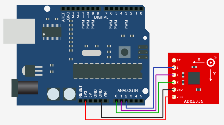
Testing with Arduino board, sample program is shown below. Using this program we are reading output from X,Y and Z axis during vibration.
|
1 2 3 4 5 6 7 8 9 10 11 12 13 14 15 16 17 18 19 20 21 22 23 24 25 26 27 28 29 30 31 32 33 34 |
int x; // x axis variable int y; // y axis variable int z; // z axis variable /************************************************************************************** Function : setup() Description : Use it to initialize variables, pin modes, start using libraries, etc. The setup function will only run once, after each power up or reset of the Arduino board. ***************************************************************************************/ void setup() { Serial.begin(9600); // opens serial port, sets data rate to 9600 bps } /************************************************************************************** Function : loop() Description : Loops consecutively, allowing your program to change and respond. Use it to actively control the Arduino board. ***************************************************************************************/ void loop() { x = analogRead(0); // read the 0th analog input pin y = analogRead(1); // read the first analog input pin z = analogRead(2); // read the second analog input pin Serial.print("X = "); // print x adc value Serial.println(x); Serial.print("Y = "); // print y adc value Serial.println(y); Serial.print("Z = "); // print z adc value Serial.println(z); delay(100); } |
Connect ADXL335 module with Arduino and upload the Arduino example code. Then open the serial monitor, ADXL335 will output the acceleration values on x, y and z axis as shown below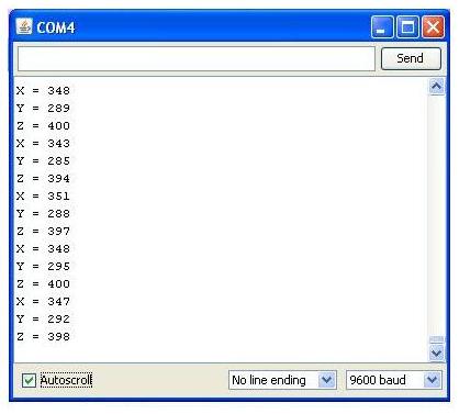
2. Testing 3 Axis Accelerometer with Regulator – ADXL335 using PIC16F877A
When interfacing 3 Axis Accelerometer with Regulator – ADXL335 with PIC16F877A micro-controller, The X,Y,Z pins of the sensor is connected to Port A of the micro-controller. Here X,Y,Z pins are connected to RA1, RA2, RA3 respectively. Connection diagram is shown below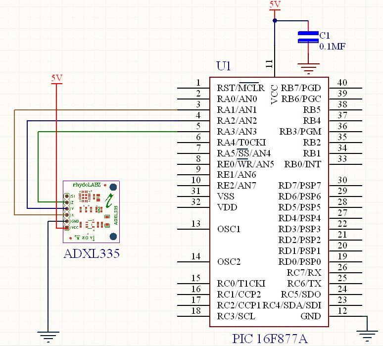
Testing 3 Axis Accelerometer with Regulator – ADXL335 with PIC16F877A, sample program is shown below. Using this program we are reading output from X,Y and Z axis during vibration.
|
1 2 3 4 5 6 7 8 9 10 11 12 13 14 15 16 17 18 19 20 21 22 23 24 25 26 27 28 29 30 31 32 33 34 35 36 37 38 39 40 41 42 43 44 45 46 47 48 49 50 51 52 53 54 55 56 57 58 59 60 61 62 63 64 65 66 67 68 69 70 71 72 73 74 75 76 77 78 79 80 81 82 83 84 85 86 87 88 89 90 91 92 93 94 95 96 97 98 99 100 101 102 103 104 105 106 107 108 109 110 111 112 113 114 115 116 117 118 119 120 121 122 123 124 125 126 127 128 129 130 131 132 133 134 135 136 137 138 139 140 |
/********************************************************************************** * Microcontroller -- PIC 16 F877 - 40-pin - 8-bit * * Clock Frequency is 20 MHz -- Period in 200 Nano Seconds * * USART - BaudRate 9600 * * This program is used to read MEMS accelermeter *******************************************************************************/ #include<pic.h> #include"delay.c" int X_Value=0; int Y_Value=0; int Z_Value=0; void ADC_init() ; void send(char); int adc_conv(int); void SerialPortInit() ; void SendData(char); void display(int value ); void MSdelay(unsigned int); static void Send2USART(const char *CPtr1); void main() { TRISC=0X80; TRISE=0X07; SerialPortInit() ; ADC_init(); while(1) { Send2USART("X-axis:"); X_Value=adc_conv(1); display(X_Value ); SendData(' '); Send2USART("Y-axis:"); Y_Value=adc_conv(2); display(Y_Value ); SendData(' '); Send2USART("Z-axis:"); Z_Value=adc_conv(3); display(Z_Value ); SendData('\n'); SendData('\r'); } } /******************************************************************************* * Function : Send2USART * Description : Group of data send serially ******************************************************************************/ static void Send2USART(const char *Cptr1) { while(*Cptr1 != '\0') { SendData(*Cptr1); Cptr1++; } } /******************************************************************************* * Function : display * Description : Display adc value function ******************************************************************************/ void display(int value ) { char k=1; char array[4]; for(k=1;k<=4;k++) { array[k]=value%10; value=value/10; } for(k=4;k>=1;k--) { SendData(array[k]+'0'); } } /******************************************************************************* * Function : SerialPortInit * Description : Usart Initialization function - Baud Rate 9600 ******************************************************************************/ void SerialPortInit() { GIE=1; SYNC=0; TXEN=1; BRGH=1; SPEN=1; CREN=1; PEIE=1; RCIE=1; SPBRG=129; } /******************************************************************************* * Function : ADC_init * Description : Adc Initialization function ******************************************************************************/ void ADC_init() { ADFM=1; PCFG3=0; PCFG2=0; PCFG1=0; PCFG0=0; } /******************************************************************************* * Function : adc_conv * Description : Adc Conversion function ******************************************************************************/ int adc_conv(int channel) { int ab; ADCON0=0x81|channel<<4; //channel selection DelayMs(1); ADGO=1; //start AD conversion while(ADGO!=0); //wiating for competion of AD conversion ab=ADRESH; //assign 2bit value ADRSH register to variable ab ab=ADRESH<<8; //8 times shift variable ab value ab=ab|ADRESL; //combine ADRESL & ab value return(ab); } /******************************************************************************* * Function : SendData * Description : Send a data serially ******************************************************************************/ void SendData(char sdata) { TXREG=sdata; while(TRMT!=1); } /******************************************************************************* * Function : MSdelay * Description : Generate 1ms delay ******************************************************************************/ void MSdelay(unsigned int val) { unsigned int del,del1; for(del=1;del<=val;del++) { for(del1=0;del1<=331;del1++); } } |
When PIC16F877A micro-controller receives 3 Axis Accelerometer with Regulator – ADXL335 datas and are displayed on serial monitor as shown below.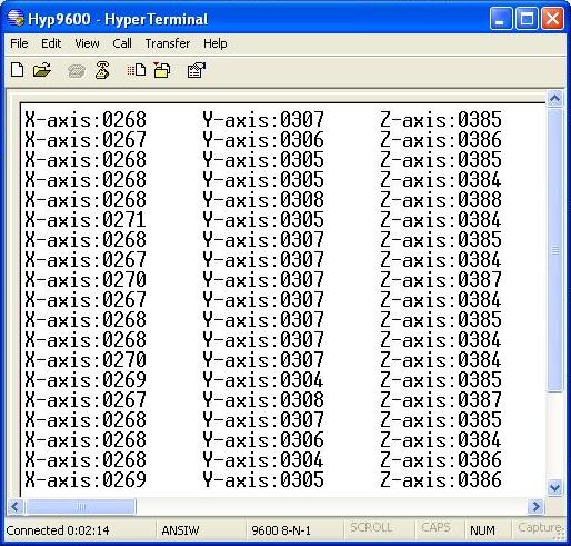
Resources:![]() Schematic
Schematic
ADXL-335 Data sheet
Example 3D cube project (PIC)
Wiring Example
Bildr Example
How to Buy:
![]() Click here to buy rhydoLABZ 3 Axis Accelerometer with Regulator – ADXL335
Click here to buy rhydoLABZ 3 Axis Accelerometer with Regulator – ADXL335
Support:![]() Please share your ideas with us, visit our forum for discussion
Please share your ideas with us, visit our forum for discussion
Frequently Asked Questions(FAQ):![]()
Q.What is an accelerometer ?
Ans: An accelerometer is an electro-mechanical device that will measure acceleration forces. These forces may be static, like the constant force of gravity pulling at your feet, or they could be dynamic – caused by moving or vibrating the accelerometer.
Q.What is range of an accelerometer?
Ans: Range is the level of acceleration supported by the sensor’s output signal specifications, typically specified in ±g. This is the greatest amount of acceleration the part can measure and accurately represent as an output. For example, the output of a ±3g accelerometer is linear with acceleration up to ±3g. If it is accelerated at 4g, the output may rail.
Q. why you are getting data even while the accelerometer is at rest?
Ans:The reading of the accelerometer when at rest is due to the zero g output (typically 2.5V, varies depending upon the accelerometer model you have). Consider a sensor in a steady state on a horizontal surface, will measure 0g in X axis and 0g in Y axis whereas the Z axis will measure 1g, this Z axis value is getting at output of the accelerometer.
Q.What is zero-g offset?
Ans: Zero-g level Offset (Off) describes the deviation of an actual output signal from the ideal output signal if there is no acceleration present. A sensor in a steady state on a horizontal surface will measure 0g in X axis and 0g in Y axis whereas the Z axis will measure 1g
Q.Where would you use an accelerometer?
Ans:There are a number of practical applications for accelerometers; accelerometers are used to measure static acceleration (gravity), tilt of an object, dynamic acceleration, shock to an object, velocity, orientation and the vibration of an object. Cell phones, computers and washing machines now contain accelerometers. Other practical applications include: Measuring the performance of an automobile, measuring the vibration of a machine, measuring the motions of a bridge, measuring how a package has been handled .

Leave a Reply
You must be logged in to post a comment.