Familiarization of ARM7 : Code, Compile & load
Coding is done using Keil uVision4 IDE (Download). Procedure wise various steps are explained below.
Step 1 : Launch Keil uVision4

Step 2 : The Keil uvision window opens as shown below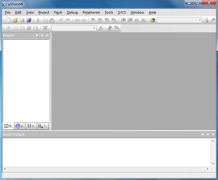
Step 3 : Create a new project, select Project > New uVision Project from menu bar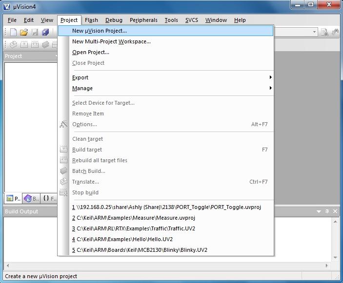
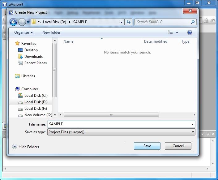
Step 4 : Create a directory for the project, and save the project files with suitable name
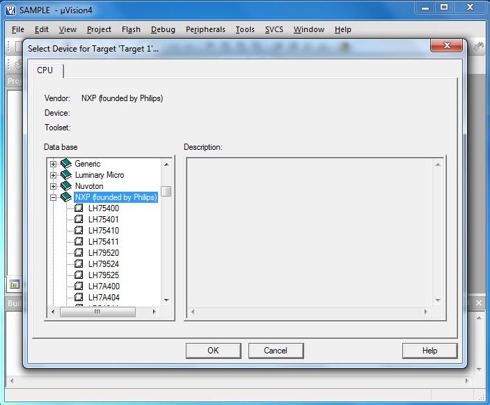
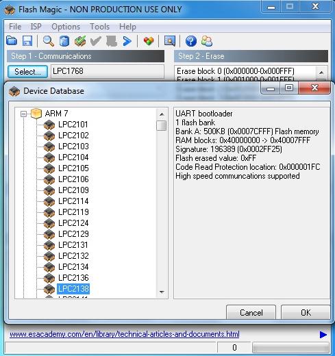
Step 5 : Select the Target Device. Here we are using LPC2138 (NXP>LPC2138) for illustration
Step 6 : Click ‘Yes’ for the following question to copy and add the Startup code to Project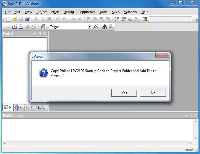
Step 7 : This creates a target to the project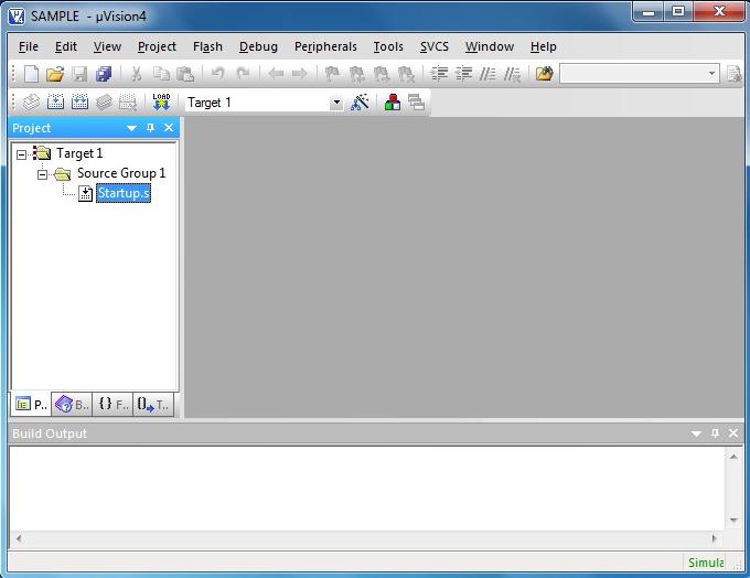
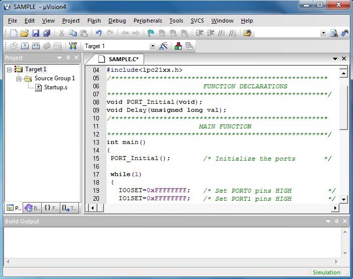
Step 8 : Open a new file (File > New) and do the necessary coding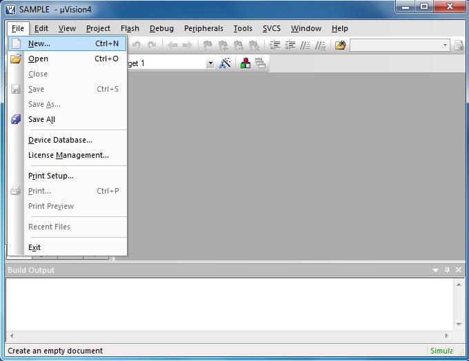
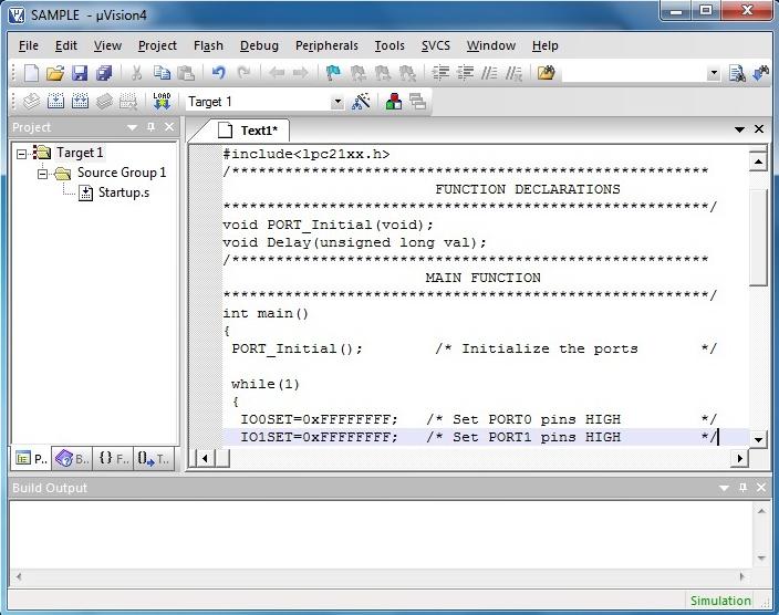
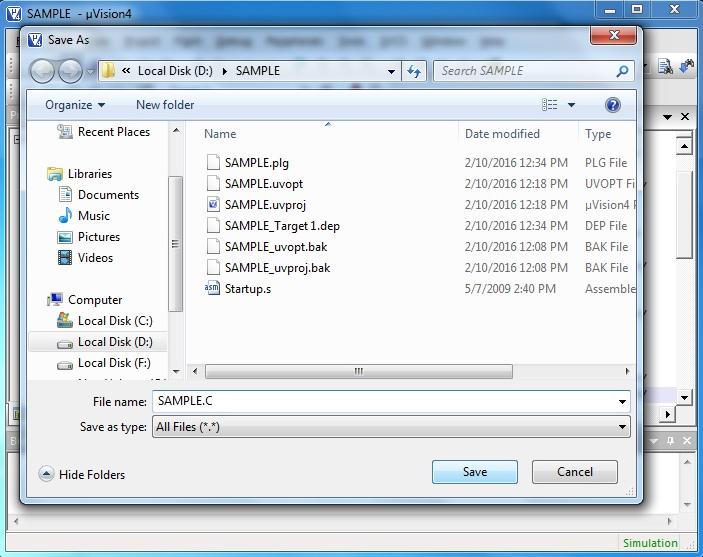
Step 9 : Save the file (File > Save) with a .c extension in the project folder
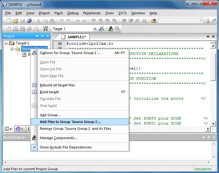
Step 10 : Right click Source Group 1 to add C file to source
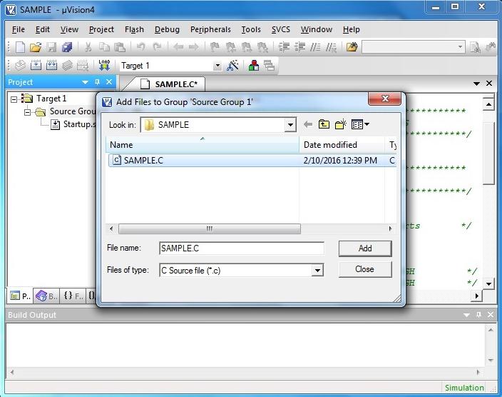
Step 11 : Select the C file created and cilck Add
Step 12 : Double click on “Startup.s” to open the configuration window and configure as below.
The PLL setup is done for 12MHz crystal. The divider (P) and multiplier (M) are selected such that the PLL output is 60MHz and and frequency of PLL current controlled oscillator is within the specified range of 156 – 320 MHz. If crystal frequency is changed, then these values must be changed accordingly.

Step 13 : Click the icon on ‘Build toolbar’ to set target file options. You can also do this by ‘Project > Options for Target ‘Target 1′ or right click on Target1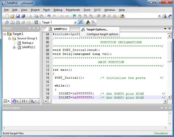
Step 14 : Configure Target, Output and Linker options as shown below
Target

Output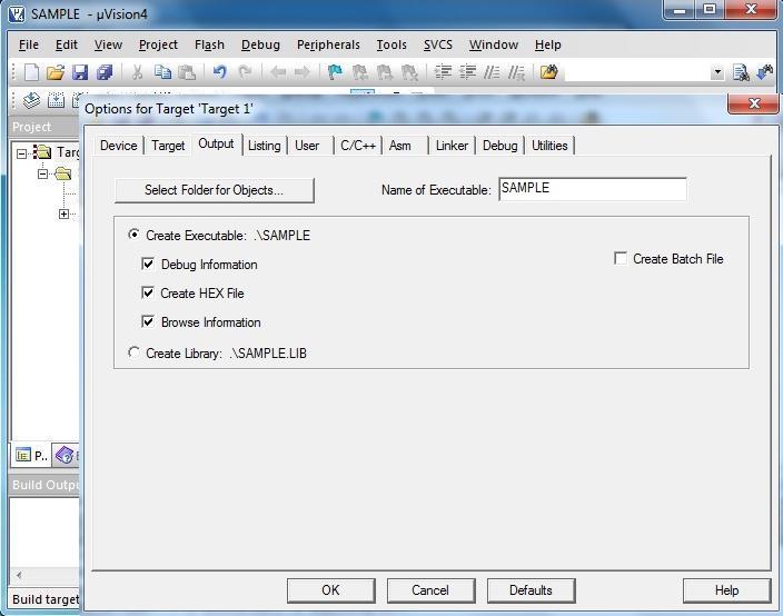
Linker
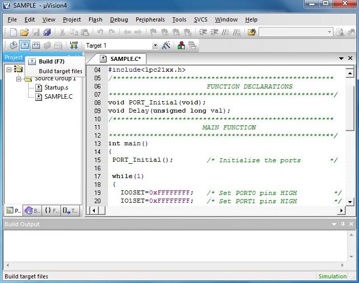
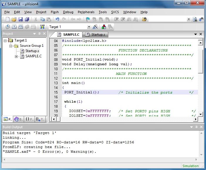
 Step 15 : Click the build icon to build the project. Errors (if any) get listed in the Build output window. Correct them and build again. On successful building, the hex file will be generated in the project folder
Once you have completed your program and generated the hex file, its time to flash it into your controller.
Flash Magic![]()
Flash Magic is a PC tool for programming flash based microcontrollers from NXP using a serial or Ethernet protocol while in the target hardware.
- Launch Flash Magic
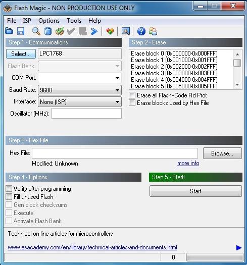
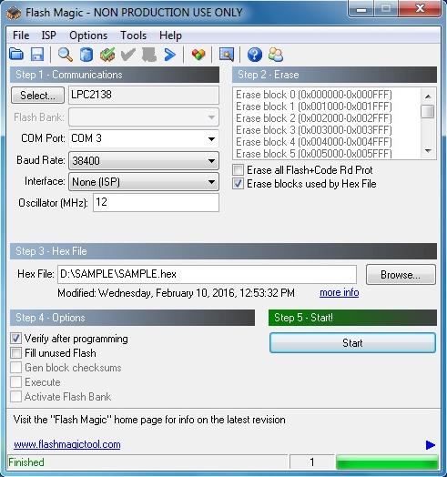
Step 1 : Communications

- Select your target device
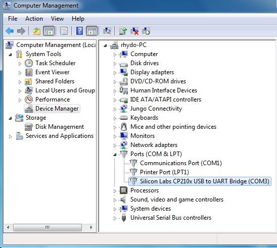
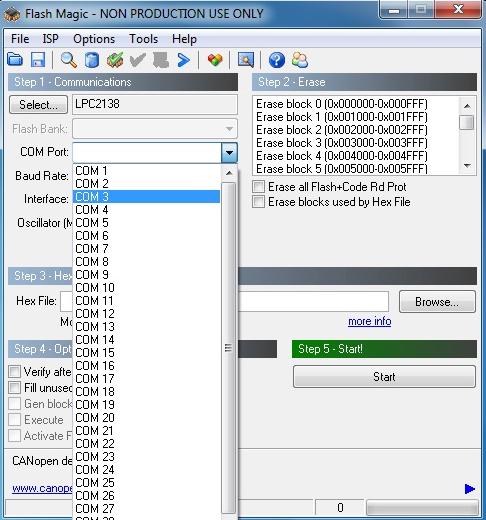
- Check for the COM port in device manager if you are using USB.
- Select your com port.
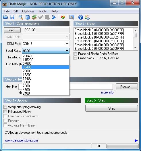
- Select baud rate for program to the target.
- Select your interface if you are using DB-9 then it will be None (ISP).
- Give your oscillator frequency in MHz.

Step 2 : Erase
- Tick erase block used hex file.

Step 3 : Hex file
- Browse the path of your Hex file which is to be loaded on chip.

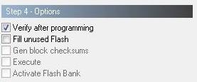
Step 4 : Options
Here always keep Verify after programming option enable by tick mark. You can use another features as well according to your need.
Step 5 : Start

Now you are all set to burn your code memory just click on start but and it will start to load hex code in your chip. You can see the process at the bottom.
Shop with us
Leave a Reply
You must be logged in to post a comment.