Getting Started with Optical Fingerprint Reader – R305
While biometrics and fingerprint identification has been existing for well over 100 years in some basic form, it is the growth of maker community that made modules like R305 and SM630 so popular. R305 and S630 are common modules used for fingerprint scanners, with the aid of a powerful DSP in its core. Basically both of these modules work the same way, we can communicate with them using a packet of hex codes in a specific format. However, the commands for operation can vary from module to module, for which we should have its datasheet. Well, for now we have the R305 here, just tested it with the products demo software from SFG. Though these have no good English documentation, SFG has done a real good work with the demo software (except the bad UI 😛 ). So.. thats it! Lets get started.
Pinout
The first 4 pins are for serial communication with default baudrate of 57600. User may set the baud rate in 9600 -115200 bps. Pins 5 – 8 are for USB communication.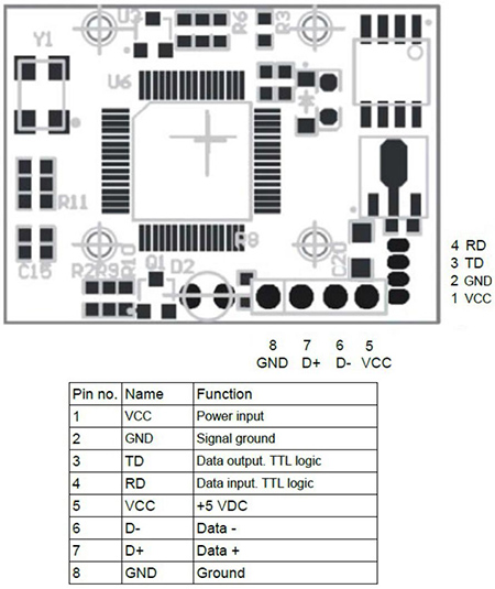
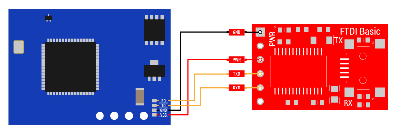
Connection Diagram
Connect the fingerprint reader to the computer via USB-serial converter. The connection diagram shown here uses the breakout board for the FTDI FT232RL USB to serial IC. Another good option is the CP2102 basic board for the USB to serial conversion. You can find variety of converters here.
If you use USB data from reader, you need not use this converter.
Once all the necessary connections are made, connect the setup to PC using USB miniB Cable. The cable is used both for powering the system and for communication between the system and PC. When powered on, it usually takes about 500ms for initialization. During this period, the module can’t accept commands. The red LED on the scanner pad blinks during this time, this indicates that the sensor is working.
Module address
Each module has an identifying address. When communicating another system, each instruction/data is transferred in data package form, which contains the device address. Module responds only to data package whose address value is the same with its identifying address. The address length is 4 bytes, and its default factory value is 0xFFFFFFFF. User may modify the address via instruction. The new modified address remains at power off.
Communication Protocol
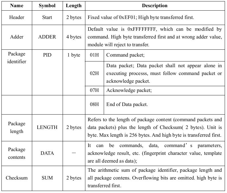
When communicating, the transferring of command/data/result are all in a specific data package format. The data package format for communication is shown below:

Thus a data package transferred to or from the module will include a Header, Address, Package Identifier, Package Length, Package Content, Checksum. Consider an example here:
EF 01 FF FF FF FF 01 00 03 01 00 05
The example shown above asks the module to collect the finger image. For more details on the data package contents see the table below:
New user enroll with software:
We found a compatible software for the module, which made it really easy to add, search fingerprints. Download link for the software is provided at the bottom of this page, below we have the step by step procedure for adding a new fingerprint using this software:
1. Start up the software
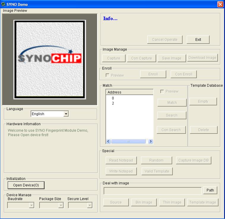
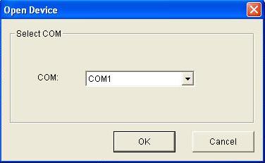
2. Click Open Device (in the bottom left corner). A new window opens up. Select the COM port used by the USB – serial converter (You can get the COM port from the device manager) and press OK when done.
Note : Our attempts ran into trouble when the COM port assigned was >10. Changing it to something <10 solved the issue
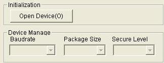
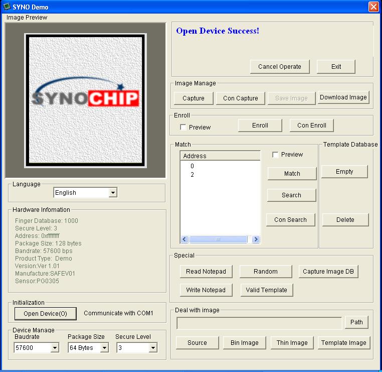
You can see the following blue success message and some device statistics such as Baudrate, Package size and Security level in the bottom corner. You can change the baud rate in the bottom left hand corner as well as the security level (how sensitive it is) but we suggest leaving those alone until you have everything running and you want to experiment. They should default to 57600 baud and security level 3 so set them if they’re wrong
On the other hand, if there is any connection error or if the default address/password has been modified, you will get an error message.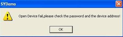
3. Now its time to enroll a new finger! Click the Preview checkbox and press the Enroll button next to it (See the red box). Con Enroll means Continuous enroll which you can use if you have many fingers to enroll. When the box comes up enter the ID you want to use. You can use up to 162 ID numbers .
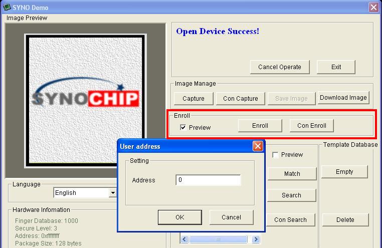
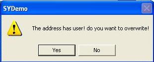
If the given ID is already used, then the software asks for overwrite. Click Yes for replacing the existing fingerprint. If you do not wish to replace, then click No and give new ID
4. Once the ID is given, the software will ask you to press the finger to the sensor. Now the LED blinks rapidly. You can place your finger on the window.
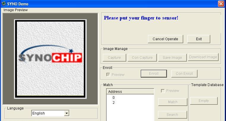
You can then see a preview (if you clicked the preview checkbox) of the fingerprint
![]()
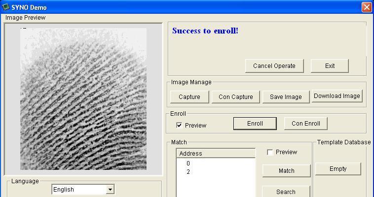
You will have to place the finger once again to get a second clean print. Use the same finger.
On success you will get a notice.
If there’s a problem such as a bad print or image you’ll get an error message and have to do it again.
Interfacing with Arduino
It is quite easy to use the fingerprint reader with Arduino by using this library from Github. It uses software serial pins to communicate with the reader. The connections should be as follows
Note : The ‘enroll’ example in the Github repository worked properly only when line no: 64 was commented.
Resources
Shop With Us
Leave a Reply
You must be logged in to post a comment.