3 Axis Accelerometer with Regulator – ADXL345
Accelerometers are devices that measure acceleration, which is the rate of change of the velocity of an object. They measure in meters per second squared (m/s2) or in G-forces (g). A single G-force for us here on planet Earth is equivalent to 9.8 m/s2, but this does vary slightly with elevation (and will be a different value on different planets due to variations in gravitational pull). Accelerometers are useful for sensing vibrations in systems or for orientation applications. Accelerometers can measure acceleration on one, two, or three axis. 3-axis units are becoming more common as the cost of development for them decreases.
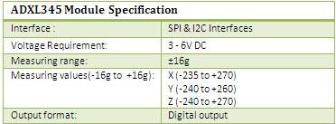
The ADXL345 is a complete 3-axis acceleration measurement system with a selectable measurement range of ±2 g, ±4 g, ±8 g, or ±16 g. It measures both dynamic acceleration resulting from motion or shock and static acceleration, such as gravity, which allows the device to be used as a tilt sensor.
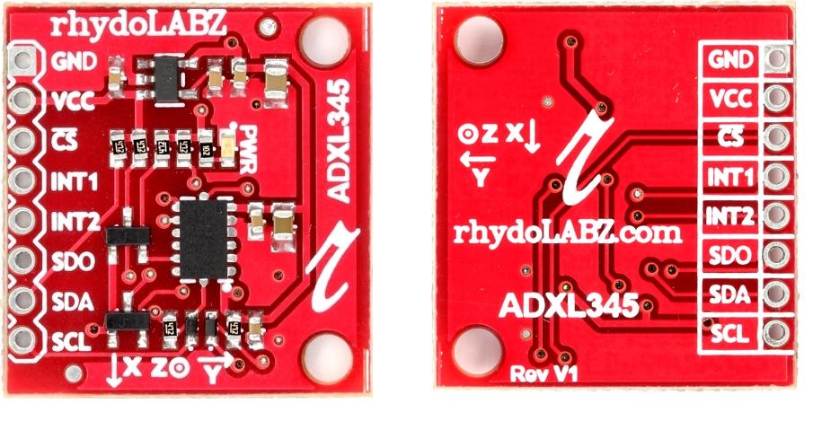
Rhydolabz’s ADXL345 is a 3 Axis Accelerometer with Voltage regulator onboard. The module is populated with MOSFET based Voltage level conversion circuitry to enable you to interface different type of microcontrollers (3V3 & 5V) . Apart from the above all necessary components like decoupling capacitors , filter capacitors ,Pull up resistors and LED are also populated on board. So out of the box you are ready to go.
The ADXL345 is a small, thin, low power, 3-axis accelerometer with high resolution (13-bit) measurement at up to ±16 g. Accelerometers with a digital interface can either communicate over SPI or I2C communication protocols. These tend to have more functionality and be less susceptible to noise than analog accelerometers. Digital output data of ADXL345 is formatted as 16-bit two’s complement and is accessible through either a SPI (3- or 4-wire) or I2C digital interface. The ADXL345 is well suited to measures the static acceleration of gravity in tilt-sensing applications, as well as dynamic acceleration resulting from motion or shock. Its high resolution (4 mg/LSB) enables measurement of inclination changes less than 1.0°.
Several special sensing functions are provided. Activity and inactivity sensing detect the presence or lack of motion and if the acceleration on any axis exceeds a user-set level. Tap sensing detects single and double taps. Free-fall sensing detects if the device is falling. These functions can be mapped to one of two interrupt output pins. An integrated, patent pending 32-level first in, first out (FIFO) buffer can be used to store data to minimize host processor intervention. Low power modes enable intelligent motion-based power management with threshold sensing and active acceleration measurement at extremely low power dissipation.
Features:
- 3V-6V DC Supply Voltage
- Onboard LDO Voltage regulator
- Built in Voltage level convertor (MOSFET based)
- Can be interface with 3V3 or 5V Microcontroller.
- All necessary Components are populated.
- Ultra Low Power: 40uA in measurement mode, 0.1uA in standby@ 2.5V
- Tap/Double Tap Detection
- Free-Fall Detection
- SPI and I2C interfaces

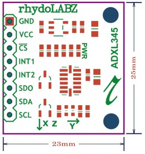 How To Test :
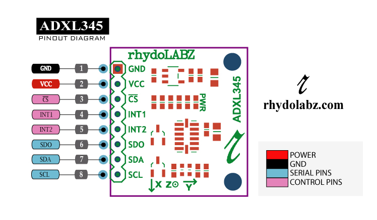
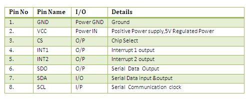
Here is the guide illustrates how to connect an Arduino to the ADXL345 Triple Axis Accelerometer. The following picture describes which pins on the Arduino should be connected to the pins on the accelerometer:
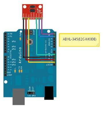
Testing with Arduino board, sample program is shown below. Using this program we are reading output from X,Y and Z axis during vibration.
|
1 2 3 4 5 6 7 8 9 10 11 12 13 14 15 16 17 18 19 20 21 22 23 24 25 26 27 28 29 30 31 32 33 34 35 36 37 38 39 40 41 42 43 44 45 46 47 48 49 50 51 52 53 54 55 56 57 58 59 60 61 62 63 64 65 66 67 68 69 70 |
#include <Wire.h> #define DEVICE (0x53) //ADXL345 device address #define TO_READ (6) //num of bytes we are going to read each time (two bytes for each axis) byte buff[TO_READ] ; //6 bytes buffer for saving data read from the device char str[512]; //string buffer to transform data before sending it to the serial port void setup() { Wire.begin(); // join i2c bus (address optional for master) Serial.begin(9600); // start serial for output //Turning on the ADXL345 writeTo(DEVICE, 0x2D, 0); writeTo(DEVICE, 0x2D, 16); writeTo(DEVICE, 0x2D, 8); } void loop() { int regAddress = 0x32; //first axis-acceleration-data register on the ADXL345 int x, y, z; readFrom(DEVICE, regAddress, TO_READ, buff); //read the acceleration data from the ADXL345 //each axis reading comes in 10 bit resolution, ie 2 bytes. Least Significat Byte first!! //thus we are converting both bytes in to one int x = (((int)buff[1]) << 8) | buff[0]; y = (((int)buff[3]) << 8) | buff[2]; z = (((int)buff[5]) << 8) | buff[4]; //we send the x y z values as a string to the serial port sprintf(str, "%d %d %d", x, y, z); Serial.print(str); Serial.print(10, BYTE); //It appears that delay is needed in order not to clog the port delay(15); } //---------------- Functions //Writes val to address register on device void writeTo(int device, byte address, byte val) { Wire.beginTransmission(device); //start transmission to device Wire.send(address); // send register address Wire.send(val); // send value to write Wire.endTransmission(); //end transmission } //reads num bytes starting from address register on device in to buff array void readFrom(int device, byte address, int num, byte buff[]) { Wire.beginTransmission(device); //start transmission to device Wire.send(address); //sends address to read from Wire.endTransmission(); //end transmission Wire.beginTransmission(device); //start transmission to device Wire.requestFrom(device, num); // request 6 bytes from device int i = 0; while(Wire.available()) //device may send less than requested (abnormal) { buff[i] = Wire.receive(); // receive a byte i++; } Wire.endTransmission(); //end transmission } |
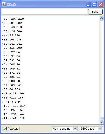
Connect ADXL345 module with Arduino and upload Arduino example code. Then open serial monitor, ADXL345 will gives acceleration values on x, y and z axis as shown below
Resources: Schematic
ADXL-345 Data sheet
How to Buy:
 Click here to buy rhydoLABZ 3 Axis Accelerometer with Regulator – ADXL345
Support: Please share your ideas with us, visit our forum for discussion
Frequently Asked Questions(FAQ):
Q.What is an accelerometer ?
Ans: An accelerometer is an electro-mechanical device that will measure acceleration forces. These forces may be static, like the constant force of gravity pulling at your feet, or they could be dynamic – caused by moving or vibrating the accelerometer.
Q.What is range of an accelerometer?
Ans: Range is the level of acceleration supported by the sensor’s output signal specifications, typically specified in ±g. This is the greatest amount of acceleration the part can measure and accurately represent as an output. For example, the output of a ±3g accelerometer is linear with acceleration up to ±3g. If it is accelerated at 4g, the output may rail.
Q. why you are getting data even while the accelerometer is at rest?
Ans:The reading of the accelerometer when at rest is due to the zero g output (typically 2.5V, varies depending upon the accelerometer model you have). Consider a sensor in a steady state on a horizontal surface, will measure 0g in X axis and 0g in Y axis whereas the Z axis will measure 1g, this Z axis value is getting at output of the accelerometer.
Q.What is zero-g offset?
Ans: Zero-g level Offset (Off) describes the deviation of an actual output signal from the ideal output signal if there is no acceleration present. A sensor in a steady state on a horizontal surface will measure 0g in X axis and 0g in Y axis whereas the Z axis will measure 1g
Q.Where would you use an accelerometer?
Ans:There are a number of practical applications for accelerometers; accelerometers are used to measure static acceleration (gravity), tilt of an object, dynamic acceleration, shock to an object, velocity, orientation and the vibration of an object. Cell phones, computers and washing machines now contain accelerometers. Other practical applications include: Measuring the performance of an automobile, measuring the vibration of a machine, measuring the motions of a bridge, measuring how a package has been handled .



Leave a Reply
You must be logged in to post a comment.