Getting a Quick Interface with Raspberry Pi-IO Board
 Introduction
Better way to make a control system for a Real World…
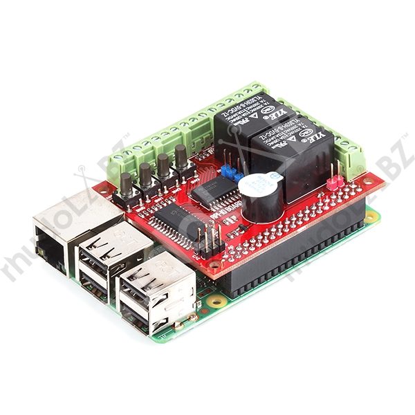
Here by we introduce a new Raspberry Pi IO Board for providing some advanced features with respect to GPIO pins in the Raspberry Pi. It is really a shield which can be mounted on to the GPIO pins of Raspberry Pi as shown in the above figure. So we just enhance the applications of GPIO pins to make a better way to connect with the real world.
Why Raspberry Pi IO Board ???
The main purpose of this board is to provide a protection to Raspberry Pi Board, as it removes the hardware connections to the GPIO pins. All the GPIO pins will be connected to this IO board and the suitable hardware modules can be connected to the board itself to perform the input and output operations.
The key features on this board will shows its relevance for communicating with the real world.
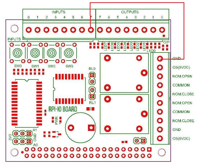
The features can be mentioned based on the Pin out diagram of IO Board.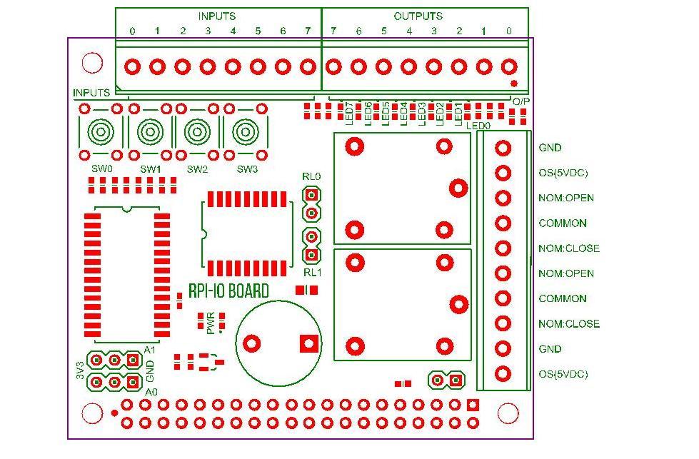 As shown in the above figure, here are the main features of this IO Board.
- 8 – Input and Output pins
- 4 Switches
- Two relays
- One Buzzer
Hardware modules can be connected to the output pins for its proper working and has the same effect of making a connection with the GPIO. There are also 8 led indications provided which shows the status of high and low outputs. Similarly for input pins can be used to connect the modules with digital output. Four switches are provided based on the input pins from 0 – 3, and by pressing the switches the state will be shown as high.
OS voltage to Pins and Relays
We can provide 5v as the OS voltage to the board from the raspberry Pi itself.
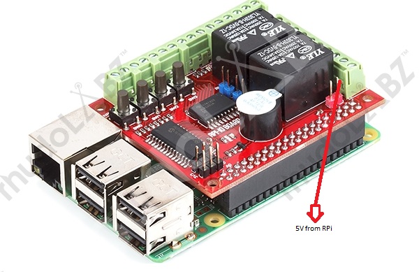 As shown in the above figure, the red arrow indicates two pins, which can be shorted using a jumper and there by the 5v from the Raspberry pi will be provided as the OS voltage to the board. We can also provide an external voltage through the OS pin for getting more voltage on the board.
If we are providing a 12V supply as OS, then the on-board relays should be disabled by removing the two jumpers in front of the relays, because the on-board relays are on 5V. So in that case a 12V relay should be connected to the output pin of the board.
Python programming for Raspberry Pi – IO Board Interface
At first we need to install the latest version of Raspbian Jessie which has an inbuilt library for Raspberry Pi IO Board. Enable the SPI interface of Raspberry Pi as the IO board work on the basis of SPI Protocol.
How to Control a single output pin on IO Board using Python Programming ???
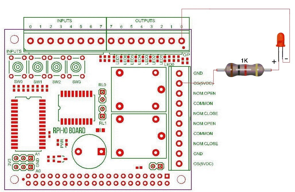
Make a connection as shown in the figure, ie the os pin should be connected to the positive side of an LED and ground pin should be connected to the 0’th output pin. For getting the 5v as output from the raspberry pi, as given above, the two pins must be shorted.
|
1 2 3 4 5 6 7 8 9 10 |
import pifacedigitalio # Library for IO Board import time pin=0 # can assign any pin number from 0 - 7 rpio = pifacedigitalio.PiFaceDigital() # creates a IO Board object rpio.output_pins[pin].value = 1 time.sleep(2) rpio.output_pins[pin].value = 0 |
By running this program the first pin output is made to active which will provide a high pulse to the connected Led and the LED0 will also move to an ON state.
Similarly by changing the pin number we an control all the 8 output pins.
|
1 2 3 4 5 6 7 8 9 10 |
import pifacedigitalio # Library for IO Board import time rpio = pifacedigitalio.PiFaceDigital() # creates a IO Board object for pin in range(8): rpio.output_pins[pin].value = 1 time.sleep(1) rpio.output_pins[pin].value = 0 time.sleep(1) |
The above code will make all the LED’s to On/Off alternatively. At the time of 7 th and 8 th pins we can see the relay will be also made to on/off as the two on board relays are connected to these pins.
To make all the led in to on/off at the same time, run the code given below:
|
1 2 3 4 5 6 7 8 |
import pifacedigitalio # Library for IO Board import time rpio = pifacedigitalio.PiFaceDigital() # creates a IO Board object rpio.output_port.all_on() time.sleep(3) rpio.output_port.all_off() |
Getting the Status of Input Pins
As we know there are 8 input pins in a Raspberry Pi IO Board. The first four pins are connected to four on board switches which produces a high value on pressing it.
The python code given below will explain how to get the status of these 8 input pins.
|
1 2 3 4 5 6 7 8 9 10 11 12 |
import pifacedigitalio import time rpio = pifacedigitalio.PiFaceDigital() # creates a PiFace Digtal while True: op=[ ] for i in range(8): ip=rpio.input_pins[i].value op.append(ip) print op time.sleep(0.2) |
While Running this code, the output will be seen in the format given below.
[0, 0, 0, 0, 0, 0, 0, 0]
[0, 0, 0, 0, 0, 0, 0, 0]
[0, 0, 0, 0, 0, 0, 0, 0]
[0, 0, 0, 0, 0, 0, 0, 0]…..
As it is in a while loop it will show continuously…
When the first button is pressed, the value in the first location of output array will become 1 and similarly for 2,3 and 4.
The pins can be made to high by connecting a wire from ground to an output pin.
So here by we can control the input and output pins of the RPi IO board and several modules can be connected to this IO Board which will not disturb the Raspberry Pi.
Shop With Us
- Click here to buy Raspberry Pi 3 from RhydoLabz.
- Click here to buy Raspberry Pi-IO Board from RhydoLabz
Leave a Reply
You must be logged in to post a comment.