4G GSM/GPRS/GPS TTL MODEM-SIM7600E
RhydoLABZ’s SIM7600E 4G/GSM/GPRS/GPS UART modem is built with Multi-Band LTE-TDD/LTE-FDD/HSPA+,works on the frequencies 2600/2300/2500/2100/1800/850/900/800 MHZ and Dual-Band GSM/GPRS/EDGE module ,works on the frequencies 900/1800 MHZ which combines GPS technology for satellite navigation.SIM7600E Modem is having internal TCP/IP stack to enable you to connect with internet via 4G/GPRS. It is suitable for Tracking, SMS, Voice as well as DATA transfer application in M2M interface and vehicle tracking applications.
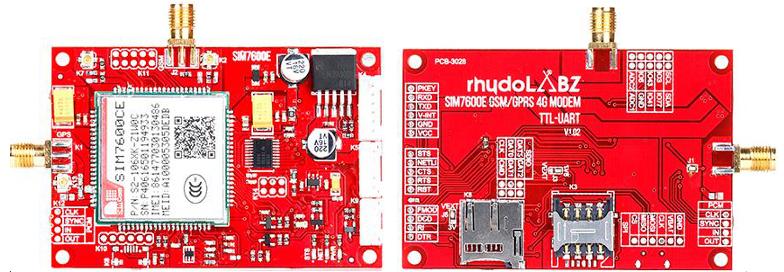
The Modem is manufactured with Automatic Pick and place machine with high quality standard.The on board Low dropout 3A Power supply allows you to connect wide range unregulated power supply (5V-12V)The baud rate is configurable from 9600-115200through AT command(default-115200) .Using this modem, you can make audio calls, SMS, Read SMS, attend the incoming calls, access internet etc through simple AT commands.The Modem is coming with selectable interfacing voltage,which allows you to connect 2V8 to 5V .This modem can operate at both TTL 3.3V and 5V Logic Level hence making it suitable for controllers at 5V logic level (PIC, AVR) as well as for 3.3V controllers like ARM based controllers and while interfacing depending upon the controller’s logic level.
Features
- TDD-LTE B38/B40/B41 2600/2300/2500 MHz
- FDD-LTE B1/B3/B5/B7/B8/B20 2100/1800/850/2600/900/800 MHz
- WCDMA/HSDPA/HSPA+ B1/B5/B8 2100/850/900 MHz
- GSM/GPRS/EDGE 900/1800 MHz
- Controlled by AT Commands.
- Supports Real Time Clock.
- Input voltage range 4.5V ~ 12V DC operation.
- Supports for eCALL.
- Integrated GPS/CNSS
- Firmware upgrade over USB interface
- Supports 3.0V to 5.0V logic level.
- Normal operation temperature: -30°C to +80°C.
- Baud rate: 300bps to 4Mbps(default:115200bps)
- Supports GPS NMEA protocol.
- Standard Micro SIM Card.
- Supply voltage range: 3.4V~ 4.2V.
GSM/GPRS SPECIFICATION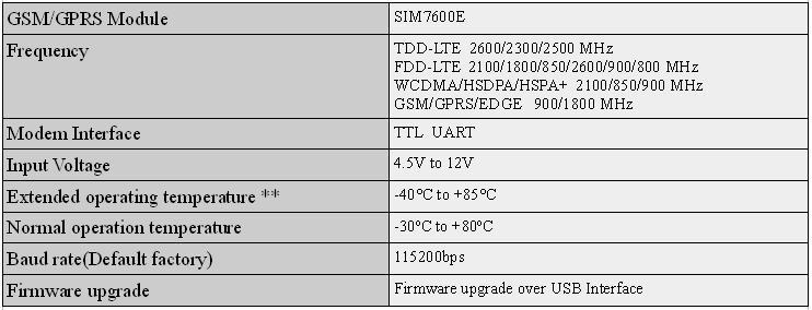
**Note: Module is able to make and receive voice calls, data calls, SMS and make GPRS/UMTS/HSPA+/LTE traffic in -40℃ ~ +85℃. The performance will be reduced slightly from the 3GPP specifications if the temperature is outside the normal operating temperature range and still within the extreme operating temperature range.
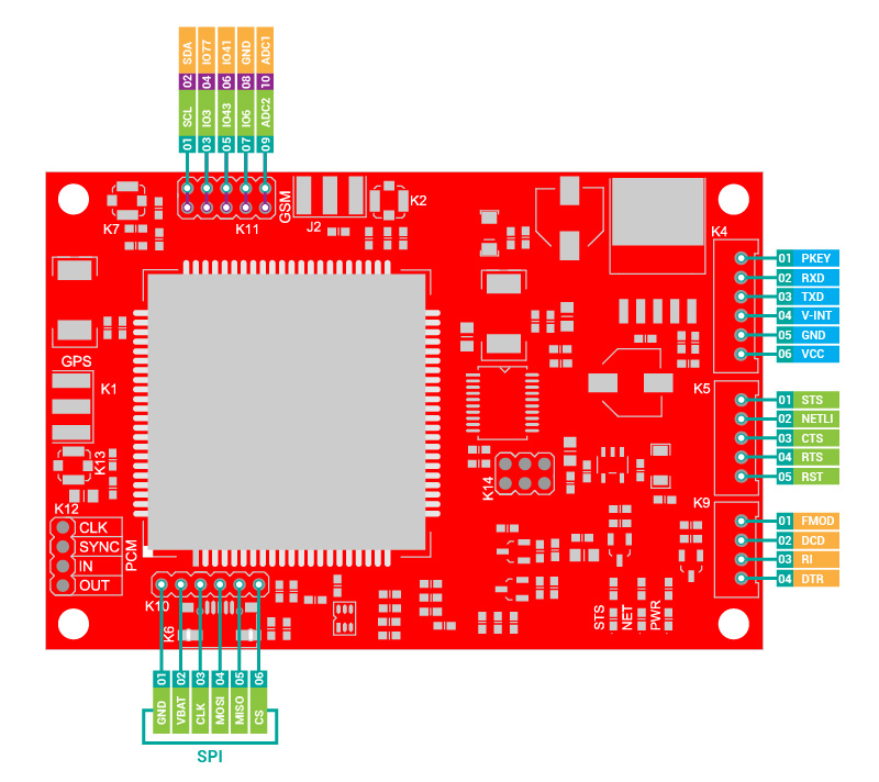
PIN DIAGRAM
DIMENSION

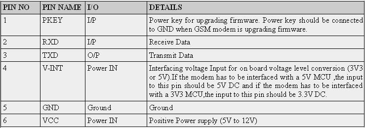
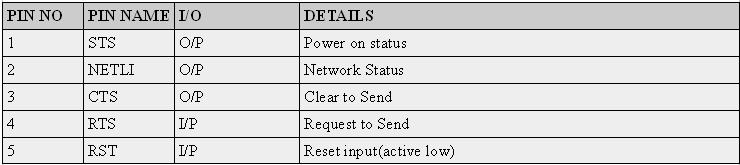
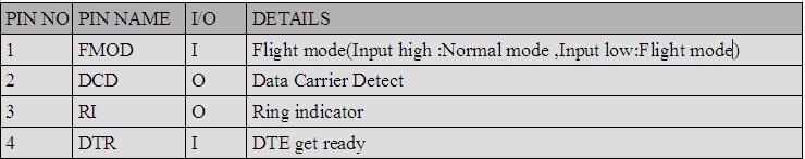
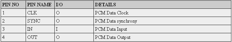
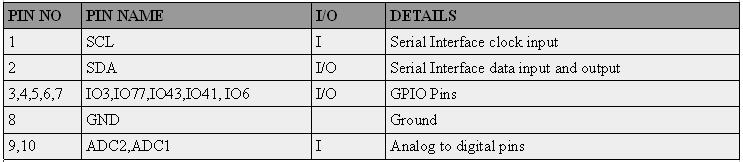
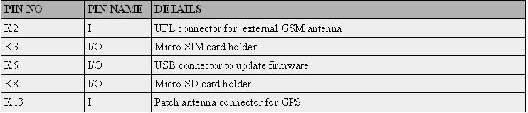
PIN DESCRIPTION
K4 RMC CONNECTOR
K5 RMC CONNECTOR
K9 RMC CONNECTOR
K12
K10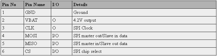
K11
K2,K3,K6,K8,K13
Getting Started
- Insert an unlocked Micro Sim card to SIM card holder. 8 pin holder for Micro SIM card is provided on the modem.
- Connect GSM Antenna to the modem.
- Connect serial cable to the modem.
- Give power supply in between 4.5V to 12V through the power jack provided.
- Default factory Baud rate is 115200.
- When the modem is successfully powered-up, the Red LED on the modem (PWR) will be ON, the STS LED(GREEN) will light after 1-2 seconds and the NET LED(BLUE) will blink every second. After the Modem registers in the network (takes between 10-60 seconds), this LED will blink in step of 3 seconds.
LED Status Description
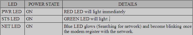
The Network LED indicates the various status of GSM module eg. Power on, Network registration & GPRS connectivity. When the modem is powered up, this NETWORK LED will glow. After the Modem registers in the network (takes between 10-60 seconds), this LED will blink in every seconds. At this stage you can start using Modem for your application,showing that modem is registered with the network.
How to Test?
Check your GSM/GPRS Modem Using DOCKLIGHT in PC:
- you need RS232 – TTL (5V) Converter or you can use FTDI Basic Breakout – 5V for making a connection between 4G/GSM/GPRS/GPS UART MODEM- SIM7600E and PC.
- Before making connection with the system you should give external supply to the modem (4.5V-12V DC) and make the ground of this supply common with GND of modem and the converter.This should be done because we cannot power the modem from the USB supply as normal operation of the modem requires a minimum current of 590 mA so its better to use a power source with 1-2A current rating.
- Firstly install a virtual serial port loading on the computer FT232RL drivers. Once the drivers are installed, connect the modem, with USB/mini-USB cable, and wait while it is found and that mean drivers are actually installed.
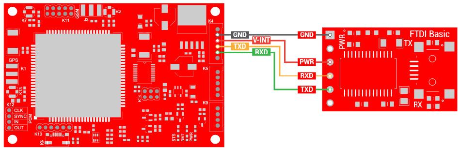
- The connection details and interfacing requirements of rhydoLABZ 4G/GSM/GPRS/GPS UART MODEM- SIM7600E with rhydoLABZ FTDI Basic Breakout-5V is as shown below
-
- Connections should be like below :
- TX(modem)-RX(converter TTL)
- RX(modem)-TX(converter TTL)
- V-INT(Modem)-PWR (converter)
- Make ground (GND-GND)common.
- Many embedded devices communicate over the serial port connection as most modern computers lack a hardware serial port;USB adapters are used to convert USB data to standard serial port data and vice versa.
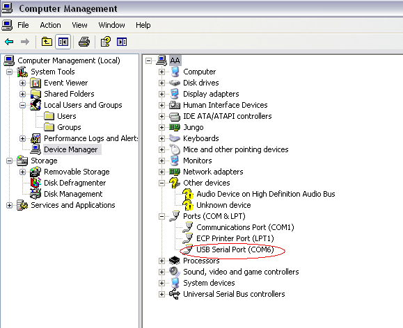
- Once you are done with all these procedures, choose the appropriate COM port that got assigned to the USB in your system by looking into the device manager like as shown below.
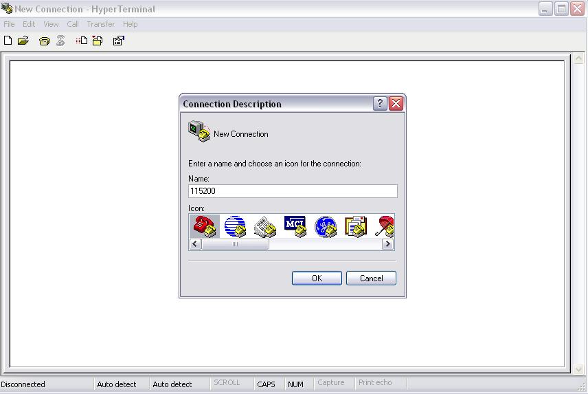
- select the serial software Hyper Terminal and Enter the name(any).
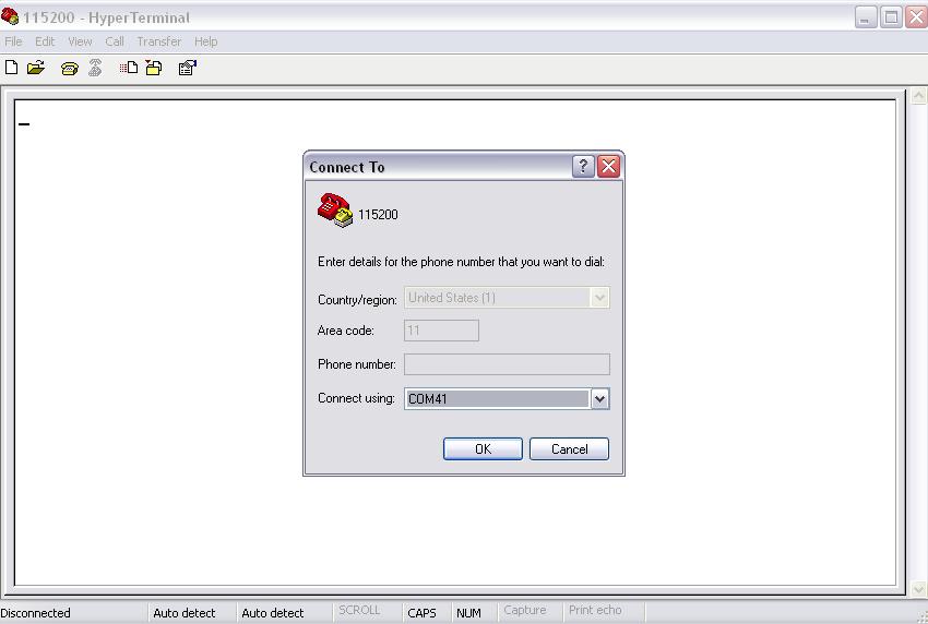
- Select the appropriate COM port(Check it on device manager).Set the baudrate which should be115200(default), parity none ,data bits 8 and stop bit 1 and flow control can also be kept as none.
 Now let’s try to check our Modem with AT commands for that we need to send following AT commands to Modem as shown below.
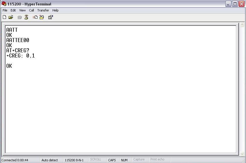 The above shown command :
- AT command (followed by enter) after “OK” response, this signifies that our Modem is working properly.
- ATE0 command (followed by enter) is being sent to stop the echo.
- AT+CREG? (followed by enter) is being used to check whether the SIM got registered or not
Sending a text message from PC using AT Commands and hyper terminal
Now next let’s send a message using rhydolabz 4G GSM/GPRS TTL MODEM- SIM7600E. For sending message we need to first send related AT commands to initialize the modem to send a message.
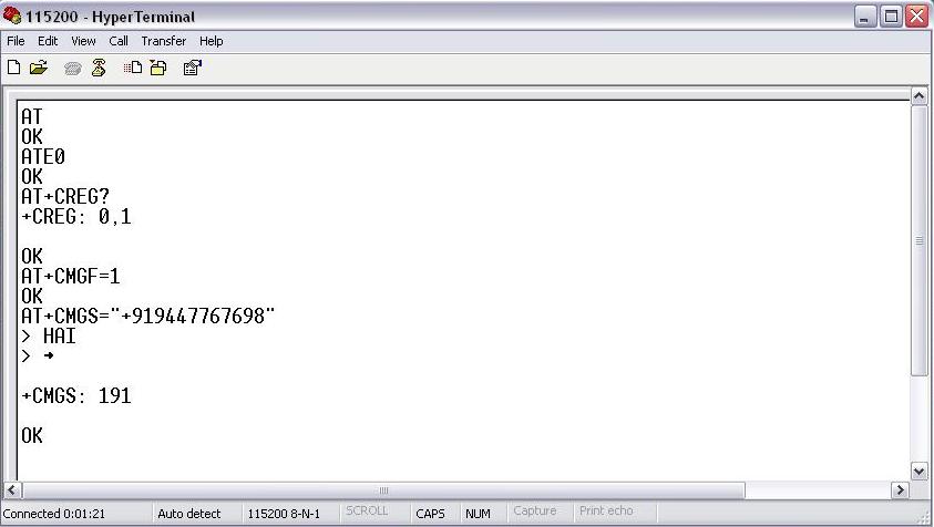
- The AT+CMGF=1 command (followed by enter) sets the GSM Modem in SMS text mode.
- AT+CMGS=<number>followed by enter gives<CR><write message><Ctrl+z>
<CR> represents the carriage return character.
<Ctrl+z>When you finish entering the SMS message body, you have to enter the <Ctrl+z> character to mark the end of the SMS message body.
+CMGS: x and OK; where x = “current number of sent SMS messages”
- Connections should be like below :
Receiving a text message in Modem and displaying in hyper terminal.
-
Now let’s receive a message using rhydolabz 4G GSM/GPRS TTL MODEM SIM7600E .For receiving message we need to first send related AT commands to initialize the modem.
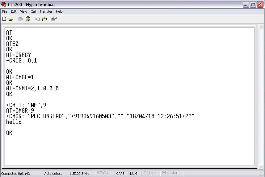
- AT+CNMI=2,1,0,0,0 command (followed by enter) set the modem to indicate received messages with +CMTI response indicates that new message has been received and shows location number of last received message in above figure it is shown by number ’9′.
- AT+CMGR=<index> :<index>integer type; value in the range of location numbers supported by the associated memory and gives +CMGR response which includes status i.e “REC UNREAD” Received unread messages, Sender’s number,date, time and received message.
Receiving a voice call from Modem using AT Commands
- For receiving call we need headset,connector jack and modem.
- Headset is connected in the marked pins of GSM Modem.
- Connections are given below
- Connect MIC -P of Modem to MIC-P of Jack.
- Connect MIC -N of Modem to MIC-N of Jack.
- Connect SPK-P of Modem to SPK-P of Jack.
- Connect SPK-N of Modem to SPK-N of Jack.
For receiving a call firstly we need to send some AT commands as shown below.
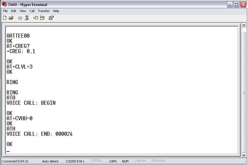
- Loudspeaker Volume Level
AT+CLVL=?
0..max – the value of max can be read by issuing the Test command
For example:
AT+CLVL=3 Command is used to select the volume of the internal loudspeaker audio - RING indicates incoming call.
- For Attending call we are using ATA command (followed by enter) gives “OK” response when call is connected.
- ATH command is used to disconnect existing call. Before using ATH command to hang up a voice call, it must set AT+CVHU=0. Otherwise, ATH command will be ignored and “OK” response is given only.
Receiving GPS location from Modem using AT Commands
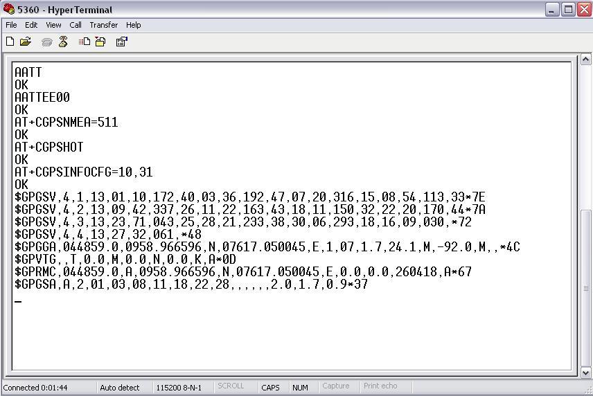
- AT+CGPSNMEA is used to configure NMEA output sentences .AT+CGPSNMEA=511(followed by enter) gives “OK” response .511 will allow all NMEA data output from Debug UART.
- AT+CGPSHOT is used to hot start GPS session.AT+CGPSHOT(followed by enter) gives “OK” response.
- AT+CGPSINFOCFG =10,31 (followed by enter) gives “OK” response.10 second is used to report NMEA sentence. 31 is used to set the whole NMEA sentence bit(s).
Testing of SD card
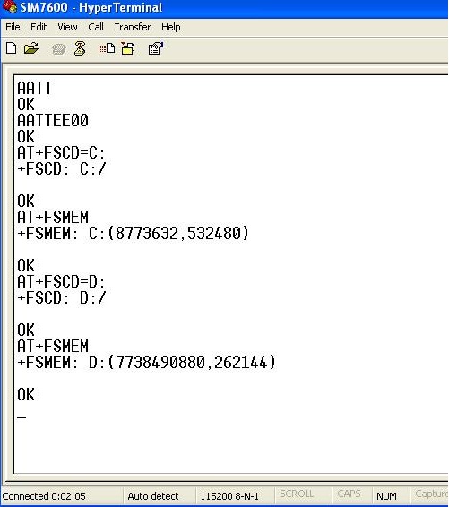
- AT+FSCD=C: is used to select the C drive(Default the module is in C drive ).
- AT+FSMEM command is used to check the Total size and Used size of internal memory(SIM7600 memory).
- AT+FSCD=D: command is used to select the D drive( We can only select this drive if we insert he SD card otherwise you will get a ERROR response for this command).
- After selecting the SD card drive when you give the AT+FSMEM command you can see the total size and used size of SD card.
Test with Arduino
- Sample code below shows how we can send a message using Arduino interfacing with modem
|
1 2 3 4 5 6 7 8 9 10 11 12 13 14 15 16 17 18 19 20 |
void setup() { Serial.begin(115200); // set the baud rate } void loop() { Serial.print("AT\r\n"); // Transmit AT to the module delay(500); // wait for a 500ms delay Serial.print("ATE0\r\n"); // Echo Off delay(500); // wait for a 500ms delay Serial.print("AT+CMGF=1\r\n"); // Switch to text mode delay(500); // wait for a 500ms delay Serial.print("AT+CNMI=2,1,0,0,0\r\n"); // Msg:settings command delay(500); // wait for a 500ms delay Serial.print("AT+CMGS=\"919874563210\"\r\n"); // Send SMS to a cell number delay(500); // wait for a 500ms delay Serial.print("\rTest SMS from rhydoLABZ.com-Cochin\r\n"); // Input SMS Data Serial.write(0x1A); // Ctrl-Z indicates end of SMS delay(500); // wait for a 500ms delay while(1); } |
NOTE: If you have any problem while using normal UART pins in Arduino boards use software serial.
- Sample code for sending SMS using software serial pins in Arduino.In this code pin 2 is Rx and 3 is TX.
|
1 2 3 4 5 6 7 8 9 10 11 12 13 14 15 16 17 18 19 20 21 22 |
#include <SoftwareSerial.h> SoftwareSerial mySerial(2, 3); // RX, TX void setup() { mySerial.begin(115200); // set the baud rate mySerial.print("AT\r\n"); // Transmit AT to the module delay(500); // wait for a 500ms delay mySerial.print("ATE0\r\n"); // Echo Off delay(500); // wait for a 500ms delay mySerial.print("AT+CMGF=1\r\n"); // Switch to text mode delay(500); // wait for a 500ms delay mySerial.print("AT+CNMI=2,1,0,0,0\r\n"); // Msg:settings command delay(500); // wait for a 500ms delay } void loop() { mySerial.print("AT+CMGS=\"9349160503\"\r\n"); // Send SMS to a cell number delay(500); // wait for a 500ms delay mySerial.print("Test MSG"); delay(500); mySerial.write(0X1A); // Ctrl-Z indicates end of SMS delay(500); // wait for a 500ms delay while(1); } |
Test with PIC16F877A
- Sample code below shows how we can send a message using PIC 16F877A interfacing with modem
|
1 2 3 4 5 6 7 8 9 10 11 12 13 14 15 16 17 18 19 20 21 22 23 24 25 26 27 28 29 30 31 32 33 34 35 36 37 38 39 40 41 42 43 44 45 46 47 48 49 50 51 52 53 54 55 56 57 58 59 60 61 62 63 64 65 66 67 68 69 70 71 72 73 74 75 76 77 78 79 80 81 82 83 84 85 86 87 88 89 90 91 92 93 94 95 96 97 98 99 100 101 102 103 104 105 106 107 108 109 110 111 112 113 114 115 116 117 118 119 |
/******************************************************************************* * Microcontroller -- PIC 16 F877 - 40-pin - 8-bit * * Clock Frequency is 20 MHz -- Period in 200 Nano Seconds * * Gsm communications are done using USART - BaudRate 9600 * * This program sends an SMS to a prefixed number when reseted. * *******************************************************************************/ #include<pic.h> /******************************************************************************* * FUNCTION DEFINITIONS *******************************************************************************/ void Delay_Ms(int ms); void Uart_Initial_Tx_Rx(unsigned long baud); void Uart_Data(unsigned char data); void Send(const char *ptr); void Send_Message(); /******************************************************************************** * CODE AREA ********************************************************************************/ void main() { Uart_Initial_Tx_Rx(115200); Send_Message(); while(1); } /******************************************************************************* * Function : Uart_Initial_Tx_Rx * Description : Usart Initialization function - Baud Rate 9600 * Parameters : baud, for selecting baurd rate *******************************************************************************/ void Uart_Initial_Tx_Rx(unsigned long baud) { TRISC6 = 0; /* Set Tx pin Output and Rx pin Input */ TXEN=1; /* Transmit Enabled */ BRGH=1; /* BaudRate = 9600 */ SYNC=0; /* Asynchronous Mode */ SPEN=1; /* Enable Serial Port */ if(baud == 9600 ) SPBRG = 129; else if (baud == 19200) SPBRG = 64; else if (baud == 38400) SPBRG = 32; else if (baud == 57600) SPBRG = 21; else if (baud == 115200) SPBRG = 10; } /******************************************************************************** * Function : Uart_Data * Description : Function to send data through the UART * Parameters : data, contains the data to be transmitted and is written to * the TXREG register ********************************************************************************/ void Uart_Data(unsigned char data) { TXREG=data; while(TRMT!=1); } /******************************************************************************** * Function : Send * Description : Function to send a string data thru USART * Parameters : ptr, contains the byte to be sent ********************************************************************************/ void Send(const char *ptr) { while(*ptr!='') { TXREG=*ptr; while(TRMT!=1); ptr++; } } /******************************************************************************** * Function : Delay_Ms * Description : Function for milliseconds at 20mhz * Parameters : ms, variable for delay ********************************************************************************/ void Delay_Ms(int ms) { int i,count; for(i=1;i<=ms;i++) { count=498; while(count!=1) { count--; } } } /******************************************************************************** * Function : Send_Message * Description : Function to send commands for sending sms * Parameters : None ********************************************************************************/ void Send_Message() { Send("AT\r\n"); /* Transmit AT to the module */ Delay_Ms(500); /* 500ms delay */ Send("ATE0\r\n"); /* Echo Off */ Delay_Ms(500); /* 500ms delay */ Send("AT+CMGF=1\r\n"); /* Switch to text mode */ Delay_Ms(500); /* 500ms delay */ Send("AT+CNMI=2,1,0,0,0\r\n"); Delay_Ms(500); /* 500ms delay */ Send("AT+CMGS=\"919874563210\"\r\n"); /* Send SMS to a cell number */ Delay_Ms(500); /* 500ms delay */ /* Input SMS Data */ Send("\rTest SMS from rhydoLABZ.com-Cochin\r\n"); Uart_Data(0x1A); /* Ctrl-Z indicates end of SMS */ Delay_Ms(500); /* 500ms delay */ } /******************************** END ******************************************/ |
Leave a Reply
You must be logged in to post a comment.