IoT Wifi Board With SMPS (4 Digital + 1 Analog)

IoTLABZ introduces a new IOT ESP8266 board with 4+1 Input. This is a 4 digital input board and an ADC pin which has esp8266 on board chip and also has 100-230VAC to 5V DC converter on the same board. It can be programmed using FTDI/CP2102. The board is manufactured with Automatic Pick and place machine with high quality standard. We can control the on-board pins from the cloud using wifi connectivity or develop your own firmware.

Here we are giving a simple experiment to read the digital pins and sending the status to a Client. For example we are connecting switches on the IO pins, read the status and sending to a Client.
FEATURES
- Based on ESP-07 ESP8266 Wifi Board.
- Onboard SMPS module is used to convert 120V-230V AC to 5V DC.
- Two pin screw terminals are used to connect Input AC .
- Eight pin RMC connector for connecting four Input.
- Three pin RMC connector for connecting Input ADC .
- Onboard programming using FTDI/CP2102.
Connectors

Before programming in Arduino IDE, we want to first install third party package using board manager.
- Install Arduino from Arduino website.
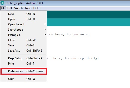
- Start Arduino and open ‘PREFERENCES‘ from ‘FILE‘ menu.
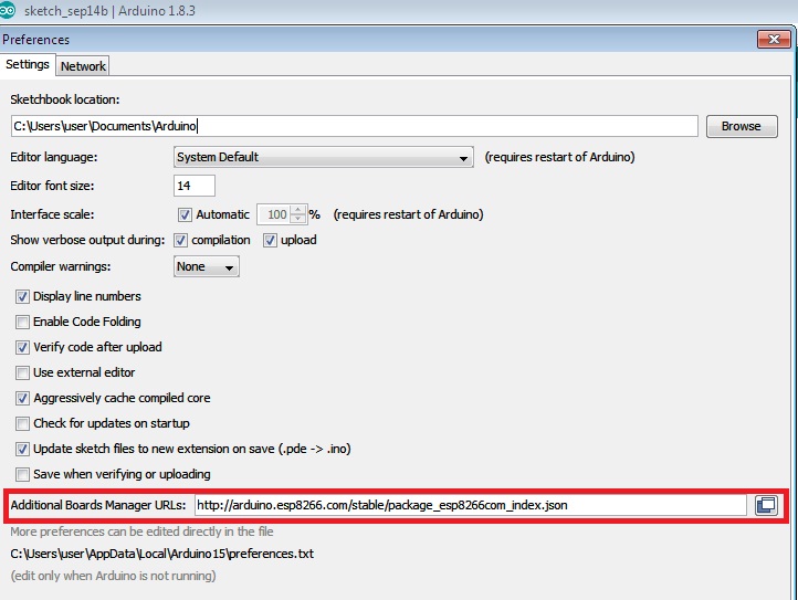
- Enter http://arduino.esp8266.com/stable/package_esp8266com_index.json into additional board manager URL field. We can add multiple URL separating them with commas.
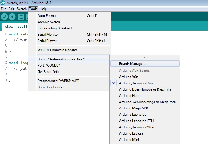
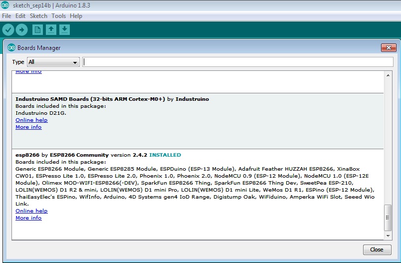
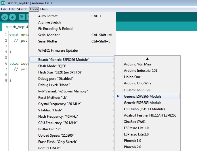
- Open Board Manager from Tools and install esp8266 platform in the Board menu
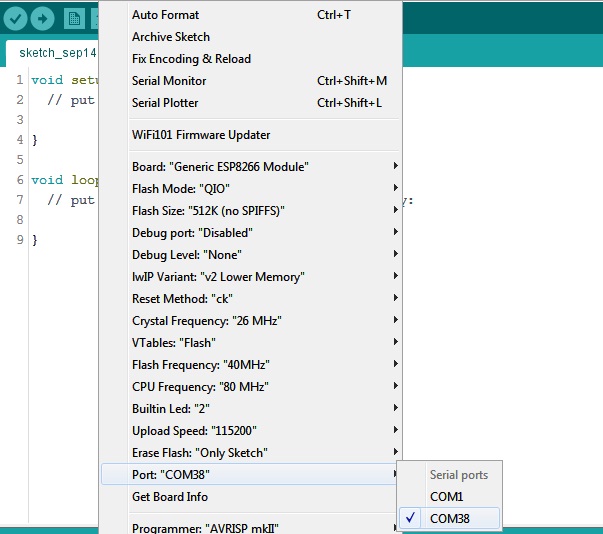
- Select the Board and COM port of the device to be connected.
In this post an android application is used to control the IOT relay board. An Application running on Android phone will get the sensor value from IOT device and it will be displayed on the Application. The four relay on the board are controlled using the Android Application.
HARDWARE CONNECTIONS
- Power the module by connecting the Line and Neutral to screw terminal connector (K4).
- Connect the sensor to RMC connector (K1).
- Connect the Input devices (Switch) to K2 and upload the code.
How to Upload code to IOT Relay board
- Put J1 jumper .
- Connect the FTDI on the connector(K3).
- Press the Reset button on the board.
- Press the Upload button on Arduino IDE.
How to connect the board to android application
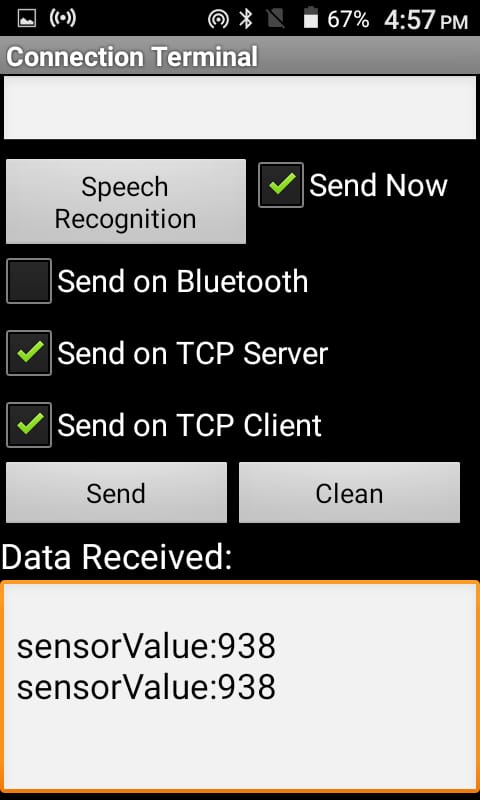
- In our examples the IOT Relay board is set as Server and it is connected to a router. The mobile is connected to the same router.The Android Application is connected to the IOT Relay board using TCP/IP protocol (Here we are using Connection terminal).

- Enter the IP and Port number and press connect button in connection terminal .
 After connecting open terminal


|
1 2 3 4 5 6 7 8 9 10 11 12 13 14 15 16 17 18 19 20 21 22 23 24 25 26 27 28 29 30 31 32 33 34 35 36 37 38 39 40 41 42 43 44 45 46 47 48 49 50 51 52 53 54 55 56 57 58 59 60 |
#include <ESP8266WiFi.h> const char* ssid = "***********"; const char* password = "***********"; WiFiServer server(2050); const int buttonPin1 = 4; // the number of the pushbutton pin const int buttonPin2 = 5; // the number of the pushbutton pin const int buttonPin3 = 12; // the number of the pushbutton pin const int buttonPin4 = 13; // the number of the pushbutton pin int SW1=0,SW2=0,SW3=0,SW4=0; void setup() { // put your setup code here, to run once: pinMode(buttonPin1,INPUT); pinMode(buttonPin2,INPUT); pinMode(buttonPin3,INPUT); pinMode(buttonPin4,INPUT); Serial.begin(115200); // Connect to WiFi network Serial.println(); Serial.println(); Serial.print("Connecting to "); Serial.println(ssid); WiFi.begin(ssid, password); while (WiFi.status() != WL_CONNECTED) { delay(500); Serial.print("."); } Serial.println(""); Serial.println("WiFi connected"); // Print the IP address Serial.println(WiFi.localIP()); // Start the server server.begin(); Serial.println("Server started"); } void loop() { delay(100); WiFiClient client = server.available(); if (!client) { return; } // Wait until the client sends some data Serial.println("new client"); while(client.connected()) { SW1=digitalRead(buttonPin1); SW2=digitalRead(buttonPin2); SW3=digitalRead(buttonPin3); SW4=digitalRead(buttonPin4); int h = analogRead(A0); //Reading Sensor value client.print(h); //Sending it to client delay(500); if(SW1==0){client.println("Button1 Pressed");} if(SW2==0){client.println("Button2 Pressed");} if(SW3==0){client.println("Button3 Pressed");} if(SW4==0){client.println("Button4 Pressed");} } } |
Sample code for Reading Sensor(ADC pin)
|
1 2 3 4 5 6 7 8 9 10 11 12 13 14 15 16 17 18 19 20 21 22 23 24 25 26 27 28 29 30 31 32 33 34 35 36 37 38 39 40 41 42 43 44 45 46 47 48 49 50 51 52 53 54 |
#include <ESP8266WiFi.h> const char* ssid = "**********"; const char* password = "**********"; WiFiServer server(2050); const int analogInPin = A0; int sensorValue = 0; void setup() { Serial.begin(115200); delay(10); // Connect to WiFi network Serial.println(); Serial.println(); Serial.print("Connecting to "); Serial.println(ssid); WiFi.begin(ssid, password); while (WiFi.status() != WL_CONNECTED) { delay(500); Serial.print("."); } Serial.println(""); Serial.println("WiFi connected"); // Print the IP address Serial.println(WiFi.localIP()); // Start the server server.begin(); Serial.println("Server started"); } void loop() { // Check if a client has connected WiFiClient client = server.available(); if (!client) { return; } // Wait until the client sends some data Serial.println("new client"); while(client.connected()) { sensorValue=analogRead(analogInPin); client.println(sensorValue); delay(500); while( client.available() ) // while client is connected { char Rx_data= client.read(); client.print(Rx_data); } } } |
OUTPUT
RESOURCES
How to Buy
Click here to buy IoTLabz IoT Wifi Board With SMPS (4 Digital + 1 Analog)
Leave a Reply
You must be logged in to post a comment.