4G LTE UART / USB Modem based on Quectel EC20 / EC25

Overview
The 4G LTE UART / USB modem, a high quality commercial and industrial grade product from rhydoLABZ, which is professionally designed with impedance matching RF PCB designs and, is built with IoT/M2M-optimized Multi-Band LTE module from Quectel. This Modem based on QUECTEL module, will automatically fallback to 3G UMTS/HSPA+ and 2G mode in the absence of 4G Network , which will enable you to use it across the entire country including remote villages where 4G/3G towers are less populated . Since this modem supports GNSS ,customer can make use of Geo Location identification using (GPS, GLONASS) Satellite networks.
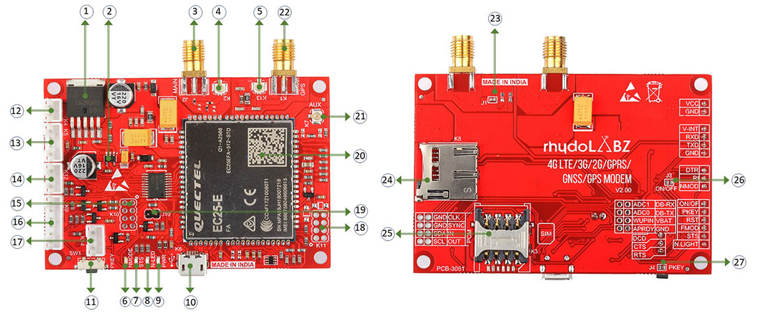
What's On Board
|
|
Modem Basic Specifications
| Communication Module | QUECTEL EC20CEFILG-128-SGNS |
| Communication Network Supported | 4G LTE, 3G , 2G, GPRS |
| GNSS (GPS) Support | Included (External Active Antenna included) |
| VoLTE Supported | Yes |
| Power Supply | 5V – 13V DC |
| Current Requirement | 300mA Normally (Peak up to 2Amp) |
| Modem Interfaces | Serial UART , USB |
| SIM Card | Micro SIM (Sliding Type) |
| SD CARD | Micro SD Card |
| Normal Operation Temperature | -40°C ~85°C |
| Serial UART Baud rate Supported | 4800bps to 921600bps ( 115200bps is Default) |
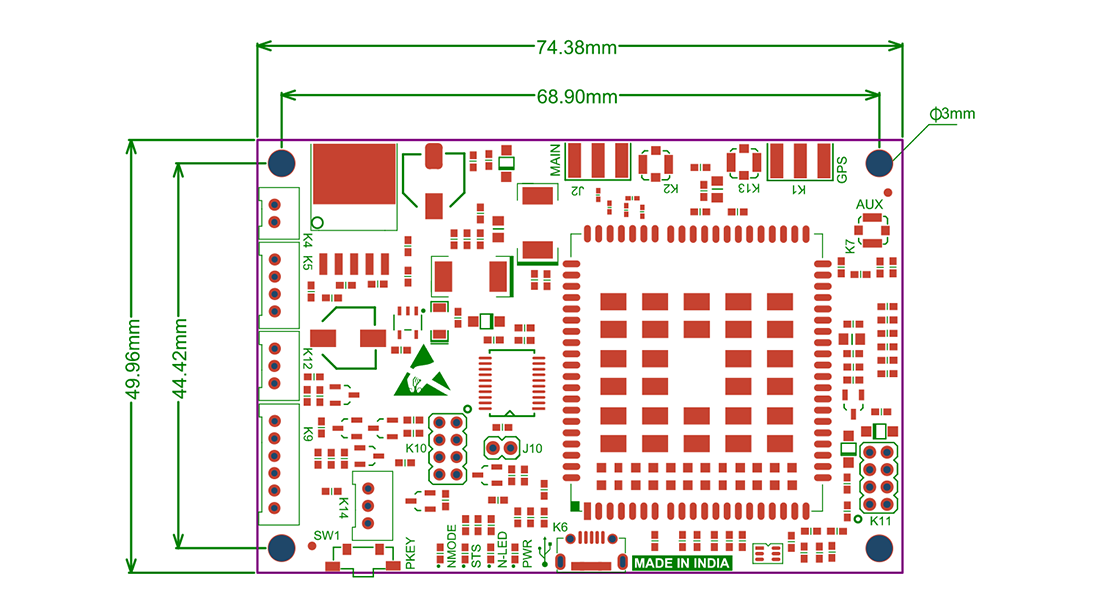
Outer Dimension of the Board
Connectors onboard
| Connector Name | Connector Details |
|---|---|
| K1 | SMA Connector for GPS External Antenna (Active or Passive) |
| K2 | UFL Connector for 4G LTE Main Antenna |
| K3 | Micro SIM Card Slot |
| K4 | Power Supply Input |
| K5 | USART Serial Communication Interface |
| K6 | USB Communication Interface |
| K7 | Diversity/Auxiliary Antenna (Optional) |
| K8 | Micro SD Card Slot |
| K9 | Control & Status Interface |
| K10 | Other I/O Pins, Debug Pins & ADC Pins for Advanced User |
| K11 | PCM Digital Audio Pins for Connecting External CODEC if needed. |
| K12 | Other MODEM O/P pins for Advanced User |
| K14 | USART Communication Hardware Handshaking Pins for Advanced user |
Pin Functions
| Connector | PIN | Name | I/O | Functions |
|---|---|---|---|---|
| K4 | ||||
| K4 | 1 | VCC | Power | Positive Power Input (5V-12V) DC Voltage |
| 2 | GND | Power | Negative Power Input (Ground) | |
| K5 | ||||
| K5 | 1 | V-INT | Power | Pin should be provided with required interfacing Voltage level. (Min 2.5V – Max 5V). Suppose user wants to interface modem with external 5V Microcontroller, then this pin should be supplied with 5V, incase of user want to interface with 3.3V Microcontroller , pin must be supplied with 3V3 , so on… |
| 2 | RXD | D.Input | USART Receive input PIN (Voltage level depends on V-INT Pin) | |
| 3 | TXD | D.Output | USART Transmit output PIN (Voltage level depends on V-INT Pin) | |
| 4 | GND | Power | Ground Return path for communication interface. | |
| K9 | ||||
|
K9 |
1 | ON/OFF | D.Input | This PIN used to turn ON or turn OFF modem power by Disabling EN pin of the internal Voltage Regulator IC. User can select either Automatic Mode or Manual mode powering option by Jumper J3. By default the PCB jumper J3 is Open and the Modem is in Automatic Powering mode. ie. once powered, Modem turned ON itself. If user wants to control the powering of the Modem manually , then the jumper should be Short and to turn ON the modem, user has to pull down ON/OFF input. if unused, keep it Short. |
| 2 | PKEY | D.Input |
Used to start and stop the modem by External microcontroller. Modem can start /stop automatically on powering or manually using this pin. A PCB jumper (J4) is provided to select this options. By default this jumper is shorted to start the Modem automatically on powering. User can remove the soldered jumper (J4) and control the modem using this pin. In manual mode, Modem can be started by applying a HIGH level pulse having a width of more than 1 Second on this Pin and later can be stopped by applying again High level pulse having a width of more than 1 Second.if unused, keep it open. |
|
| 3 | RST | D.Input | Modem can be reset by applying HIGH level pulse having a width of minimum 500 milli second. if unused, keep it open. | |
| 4 | F.MOD | D.Input | Flight Mode pin (W_DISABLE) is used to put the modem in to Airplane RF silence mode. Pull down this pin to enter Airplane mode. if unused, keep it open. | |
| 5 | STS | D.Output | It is Modem status output. It is internally pulled up to V-INT voltage level using 10k Resistor. if unused, keep it open. | |
| 6 | N.LIGHT | D.Output | It is GSM Modules NET-STATUS pin, voltage level inverted by a internal transistor. Indicate network activity status. Collector of this transistor is connected to internal LED (N-LED) and directly shared with this pin to connect external circuitry or LED through a current limiting resistor. if unused, keep it open. | |
| K10 | ||||
|
K10 |
1 | ADC1 | A.Input | General purpose analog to digital converter input 1. If unused, keep it open. #1 |
| 2 | DB-RX | D.Input | Receive debug data. If unused, keep it open. #1 | |
| 3 | ADC0 | A.Input | General purpose analog to digital converter input 0. If unused, keep it open. #1 | |
| 4 | DB-TX | D.Output | Transmit debug data. If unused, keep it open.#1 | |
| 5 | WUPIN | D.Input | WAKEUP_IN pin of the GSM module, for Sleep mode control. Cannot be pulled up before startup. Low level wakes up the module. If unused, keep it open. #1 | |
| 6 | VBAT | Power Out | GSM Module VBAT pin is made out of this pin. Can be used for powering (3v3 – 4V) any other devices like Host microcontroller etc… If unused, keep it open. | |
| 7 | APRDY | D.Output | AP_READY pin of the GSM module for application processor sleep state detection. If unused, keep it open.#1 | |
| 8 | GND | Power | Ground Return path for ADC interface. If unused, keep it open. | |
| K11 | ||||
|
K11 |
1 | OUT | D.Output | PCM data output. If unused, keep it open. #1 |
| 2 | SCL | D.I/O | PCM clock. If unused, keep it open. #1 | |
| 3 | IN | D.Input | PCM data input. If unused, keep it open.#1 | |
| 4 | SDA | D.I/O | I2C serial data. Used for external codec. If unused, keep it open.#1 | |
| 5 | SYNC | D.I/O | PCM data frame synchronization signal. If unused, keep it open. #1 | |
| 6 | GND | Power | If PCM Audio unused, keep it open. | |
| 7 | CLK | D.I/O | I2C serial clock. Used for external codec. If unused, keep it open.#1 | |
| 8 | GND | Power | If PCM Audio unused, keep it open. | |
| K12 | ||||
|
K12 |
1 | DTR | D.Input | Data terminal ready, sleep mode control pin of the GSM Module , routed after voltage level conversion. Maximum input voltage HIGH level should be same as V-INT pin voltage. if unused, keep it open. |
| 2 | RI | D.Output | Ring indicator Pin of the GSM Module, routed after voltage level conversion. Maximum output voltage HIGH level will be same as V-INT pin voltage. if unused, keep it open. | |
| 3 | N.MOD | D.Output | NET_MODE Indicate GSM module’s network registration mode, voltage level inverted by a internal transistor. Indicate network activity status. Collector of this transistor is connected to internal LED (N-LED) and directly shared with this pin to connect external circuitry or LED through a current limiting resistor. if unused, keep it open. | |
| K14 | ||||
|
K14 |
1 | DCD | D.Output | DCD (Data carrier detection) pin of the GSM Module,routed after voltage level conversion.Maximum output voltage HIGH level will be same as V-INT pin voltage. if unused, keep it open. |
| 2 | CTS | D.Output | CTS (Clear to send ) pin of the GSM Module,routed after voltage level conversion.Maximum output voltage HIGH level will be same as V-INT pin voltage. if unused, keep it open. | |
| 3 | RTS | D.Input | RTS (Request to send) pin of the GSM Module,routed after voltage level conversion.Maximum input voltage HIGH level should be same as V-INT pin voltage. if unused, keep it open. | |
- It is prohibited to supply any voltage to ADC pins when VCC or Modem Power is removed / Turned OFF.
- It is recommended to use resistor divider circuit for ADC application.
- It is recommended to use RESET only when failing to turn off the module by AT+QPOWD command or PKEY pin.
- Ensure that there is no large capacitance on PKEY and RESET pins
- In order to avoid damaging internal flash, please do not switch off the power supply when the module works normally. Only after the module is shut down by PWRKEY or AT command, the power supply can be cut off
Jumpers Onboard
| Jumper | Type | Default | Function |
|---|---|---|---|
| J1 | PCB Jumper | Short | Used to connect and disconnect 3V3 DC Voltage to GPS antenna connectors. For GPS active antenna this jumper should be shorted and for passive patch antenna it should be kept open. |
| J3 | PCB Jumper | Open |
Jumper 3 is used to select manual or automatic power controlling of the modem. By default it is open and in automatic mode ON Mode,which enable the modem to turn ON instantly upon applying the power to VCC pin. Even in this Automatic ON mode , you can control the Modem VBAT power by ON/OFF Pin on K9 connector.
In order to turn ON/OFF modem manually by external microcontroller/circuit keep this jumper short. If the jumper is shorted , modem power will be OFF , until the your microcontroller boots ,starts your application and pulling down the pin ON/OFF of K9 connector. |
| J4 | PCB Jumper | Short | It is used to ground the PKEY pin of the EC20 module permanently, which wil enable automatic starting of the modem on powering. If user would like to control the modem by manually ,either by provided SMD Tactile switch SW1 or by host microcontroller via GPIO pin, this jumper should be kept open. |
| J10 | Hardware Jumper | Open | Used to put the gsm module in USB Boot mode. |
Network Connection Status/Activity LED Indicator
| Name | Logic Level Changes | Status |
|---|---|---|
| NMODE (NET_MODE) | Always high | Registered on LTE network |
| Always low | Others | |
| NLED (NET_STATUS) | Flicker slowly (200ms high/1800ms low) | Network searching |
| Flicker slowly (1800ms high/200ms low) | Idle | |
| Flicker quickly (125ms high/125ms low) | Data transfer is ongoing | |
| Always high | Voice calling | |
| PWR (Power ON LED) | Always high | Power LED will ON once the MODEM Power Turned ON. |
| STS (Status) | Always high | Once modem starts this LED will be ON |
| SW1 (PKey Switch) | Used to start / stop the modem manually. User has to press for more than 1 Second to start / stop the modem. |
Getting Started
Test the Modem out of box using MODEM USB port.
- Insert Micro SIM card to SIM card holder provided on bottom of the Board. Please ensure the direction of SIM Notch is same as the image shown nearby.
- Connect Provided LTE Antenna to the SMA Connector marked "MAIN" on the modem. #2
- Connect GPS Antenna to the connector marked K1.
-
Install Required Quectel USB Driver software from the download link provided.(Device Manager view, before and after installations of USB Driver as below)
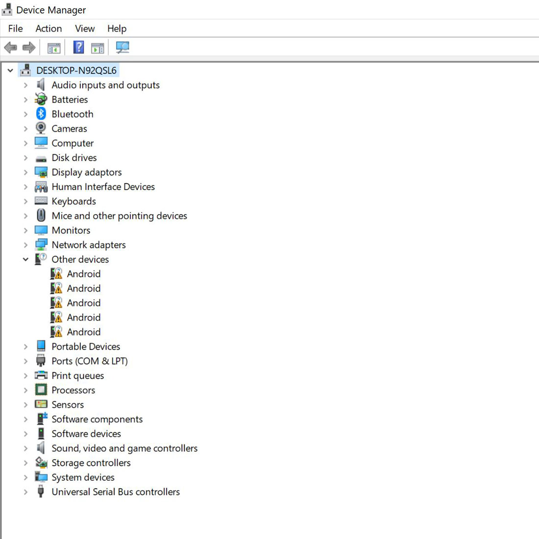
Before Installing Quectel USB Driver
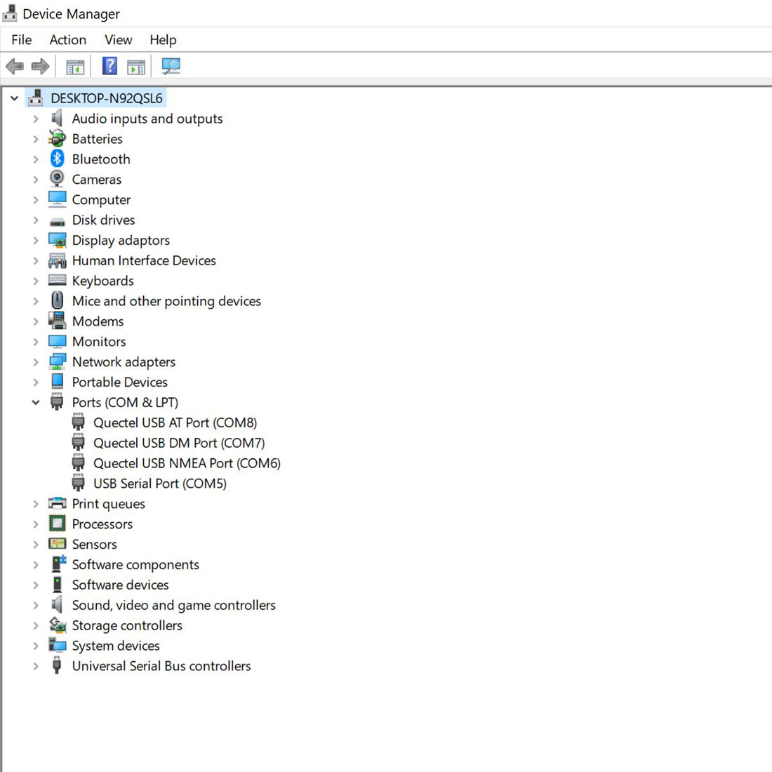
After Installing Quectel USB Driver
- Connect Micro-B USB cable to the modem (K6) from Computer.
- Connect DC Power supply to the connector K1.(Ensure Polarity)
- When the modem is successfully powered-up, the PWR LED (Red) on the modem will be ON, the STS LED(GREEN) will light after 1-2 seconds, N.MODE LED (Yellow) will turn ON and the NET LED(BLUE) will blink every second. After the Modem registers in the network (takes between 10-60 seconds), this LED will blink in step of 3 seconds.
-
Open Serial Monitor Software and select respective COM Port (AT Port) and other settings on Computer as below. #3
Default Setting are Baud rate :115200, Data bits:8 , Stop bit:1 and Parity:None -
AT<CR><LF>
Now type and send simple attention command, "AT" followed by Carriage Return("/r") and New line ("/n") Character by expecting "OK" from the modem.
Some of the Serial Monitor software will automatically append this Carriage Return/New line Character automatically or you have to add it asap.
Once you got "OK" from the modem, all set and we can proceed with other commands… -
ATE0<CR><LF>
To Turn OFF the Echo send by modem , we can issue "ATE0" followed by CR and LF. -
AT+CREG?<CR><LF>
Now we have to check whether the Modem is registered successfully with the SIM Provider Network by sending AT+CREG? followed by CR and LF.
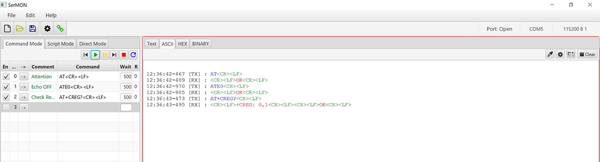
#3: User can use any available Serial Port Software like DOCKLIGHT, REAL TERM, HYPER TERMINAL or QCOM from Quectel (included in the same downloaded Driver zip file)
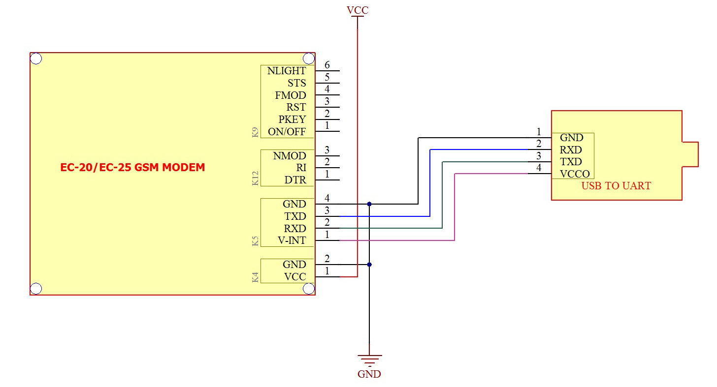
Test the Modem using USB to Serial Converter board.
- Insert Micro SIM card to SIM card holder provided on bottom of the Board. Please ensure the direction of SIM Notch is same as the image shown nearby.
- Connect Provided LTE Antenna to the SMA Connector marked "MAIN" on the modem. #2
- Connect GPS Antenna to the connector marked K1.
- Connect UART Connector K5 to the USB to Serial Converter board using provided RMC Connector Cable as per below image.
- Connect the USB Converter to the Computer and Install the required USB Driver for the Converter board ( if not installed)
-
Connect DC Power supply to the connector K1.(Ensure Polarity).
You may be able to power the modem from USB to Serial Converter board's VCC Out pin also. But this entirely depends on the Computer's USB port capability.(Not guaranteed and Recommended)
- When the modem is successfully powered-up, the PWR LED (Red) on the modem will be ON, the STS LED(GREEN) will light after 1-2 seconds, N.MODE LED (Yellow) will turn ON and the NET LED(BLUE) will blink every second. After the Modem registers in the network (takes between 10-60 seconds), this LED will blink in step of 3 seconds.
-
Open Serial Monitor Software and select respective COM Port (AT Port) and other settings on Computer as below. #3
Default Setting are Baud rate :115200, Data bits:8 , Stop bit:1 and Parity:None -
AT<CR><LF>
Now type and send simple attention command, "AT" followed by Carriage Return("/r") and New line ("/n") Character by expecting "OK" from the modem.
Some of the Serial Monitor software will automatically append this Carriage Return/New line Character automatically or you have to add it asap.
Once you got "OK" from the modem, all set and we can proceed with other commands… -
AT+QURCCFG="URCPORT","UART1"<CR><LF>
For redirecting the modem replies to the UART1 Port as well. -
ATE0<CR><LF>
To Turn OFF the Echo send by modem , we can issue "ATE0" followed by CR and LF. -
AT+CREG?<CR><LF>
Now we have to check whether the Modem is registered successfully with the SIM Provider Network by sending AT+CREG? followed by CR and LF.
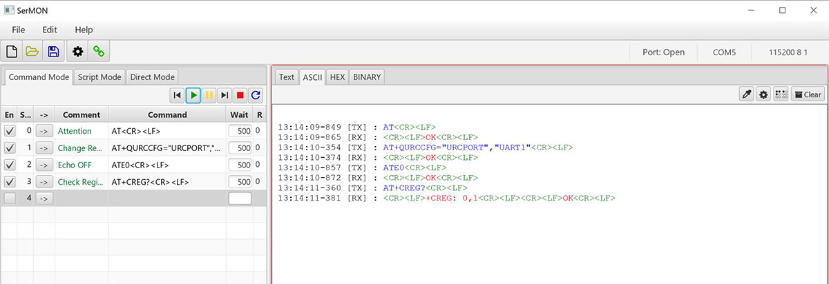
#3: User can use any available Serial Port Software like DOCKLIGHT, REAL TERM, HYPER TERMINAL or QCOM from Quectel (included in the same downloaded Driver zip file)
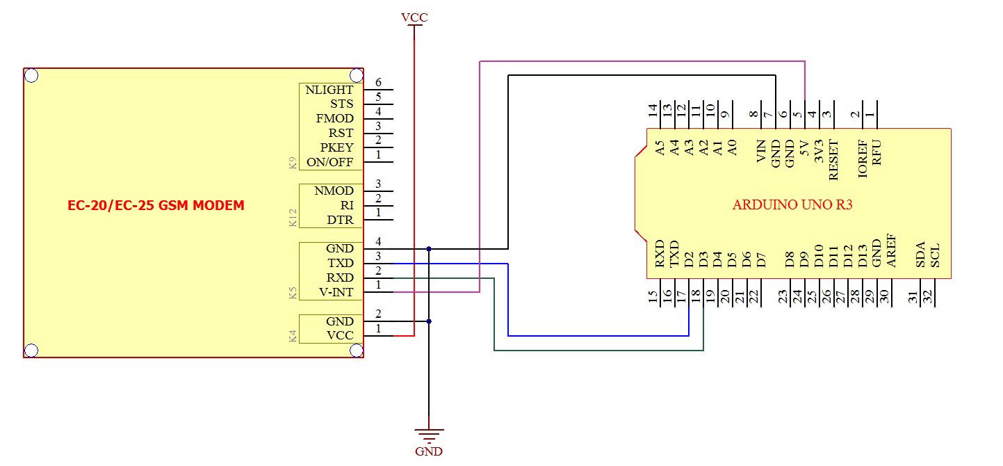
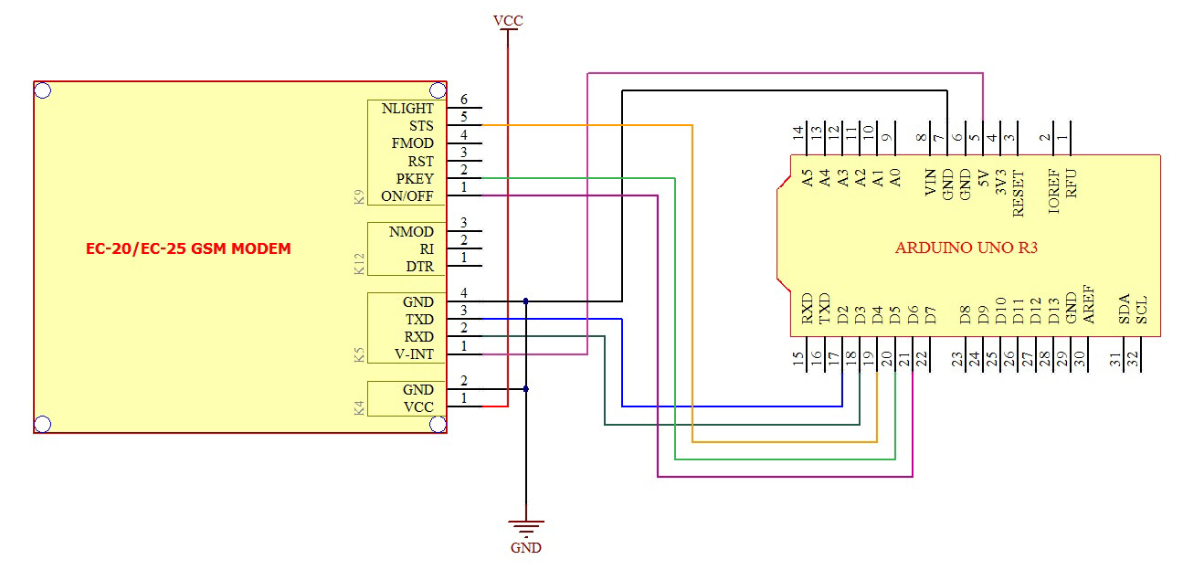
Test the Modem using Arduino UNO Board. (Basic/Simple 4 wire Connection)
- Insert Micro SIM card to SIM card holder provided on bottom of the Board. Please ensure the direction of SIM Notch is same as the image shown nearby.
- Connect Provided LTE Antenna to the SMA Connector marked "MAIN" on the modem. #1
- Connect GPS Antenna to the connector marked K1.
- Connect UART Connector K5 to the Arduino board using provided RMC Cable as per below image.
-
Connect DC Power supply to the connector K1.(Ensure Polarity).
You may be able to power the modem from ARDUINO Board VCC pin (5V-12V) also. But this entirely depends on your power supply/Arduino Board Voltage Regulator capability.(Not guaranteed by us)
- When the modem is successfully powered-up, the PWR LED (Red) on the modem will be ON, the STS LED(GREEN) will light after 1-2 seconds, N.MODE LED (Yellow) will turn ON and the NET LED(BLUE) will blink every second. After the Modem registers in the network (takes between 10-60 seconds), this LED will blink in step of 3 seconds.
-
Load the sample code provided to Arduino board and check the response on Arduino Serial Port Monitor window.
Default Setting are Baud rate :115200, Data bits:8 , Stop bit:1 and Parity:None - Once you got "OK" from the modem, all set and you can proceed with your required commands…
-
ATE0<CR><LF>
To Turn OFF the Echo send by modem , we can issue "ATE0" followed by CR and LF.
1234567891011121314151617181920#include <SoftwareSerial.h>;SoftwareSerial mySerial(2, 3); // Assign pins for RX, TXvoid setup(){mySerial.begin(115200); // set the baud rate as 115200}void loop() {mySerial.print("AT\r\n"); // Transmit AT to the moduledelay(500); // wait for a 500ms delaymySerial.print("ATE0\r\n"); // Echo Offdelay(500); // wait for a 500ms delaywhile(1); // Loop for ever}
Test the Modem using Arduino UNO Board. (Advanced Mode)
Users those who wishes to control the modem Power, Start/Stop modem manually or check the status of the modem periodically by hardware can opt the this advanced mode circuit connections as below .others can use above simple connection method.
- Remove the short on jumper J4 and keep it open.
- Ensure Jumper J3 shorted .
- Insert Micro SIM card to SIM card holder provided on bottom of the Board. Please ensure the direction of SIM Notch is same as the image shown nearby.
- Connect Provided LTE Antenna to the SMA Connector marked "MAIN" on the modem. #1
- Connect GPS Antenna to the connector marked K1.
- Connect UART Connector K5 to the Arduino board using provided RMC Cable as per below image.
-
Connect DC Power supply to the connector K1.(Ensure Polarity).
You may be able to power the modem from ARDUINO Board VCC pin (5V-12V) also. But this entirely depends on your power supply/Arduino Board Voltage Regulator capability.(Not guaranteed by us)
- When the modem is successfully powered-up, the PWR LED (Red) on the modem will be ON, the STS LED(GREEN) will light after 1-2 seconds, N.MODE LED (Yellow) will turn ON and the NET LED(BLUE) will blink every second. After the Modem registers in the network (takes between 10-60 seconds), this LED will blink in step of 3 seconds.
-
Load the sample code provided to Arduino board and check the response on Arduino Serial Port Monitor window.
Default Setting are Baud rate :115200, Data bits:8 , Stop bit:1 and Parity:None - Once you got "OK" from the modem, all set and you can proceed with your required commands…
-
ATE0<CR><LF>
To Turn OFF the Echo send by modem , we can issue "ATE0" followed by CR and LF.
12345678910111213141516171819202122232425262728293031323334353637383940414243#include <SoftwareSerial.h>;SoftwareSerial mySerial(2, 3); // Assign pins for RX, TX#define GSM_PWR_KEY 5#define GSM_STATUS_PIN 4#define POWER_ON_OFF_PIN 6void setup(){pinMode(GSM_PWR_KEY,OUTPUT); // Pin Setting as outputdigitalWrite(POWER_ON_OFF_PIN,HIGH); // Pnsure the Port Pin Register valuepinMode(POWER_ON_OFF_PIN,OUTPUT); // Pin Setting as outputpinMode(GSM_STATUS_PIN,INPUT); // Pin Setting as inputdigitalWrite(POWER_ON_OFF_PIN,LOW); // Power ON the Modemdelay(500);digitalWrite(GSM_PWR_KEY,HIGH); // Start the Modemdelay(2000);digitalWrite(GSM_PWR_KEY,LOW);while(digitalRead(GSM_STATUS_PIN) != 0) // Wait till modem is ready{}mySerial.begin(115200); // set the baud ratemySerial.print("AT\r\n"); // Transmit AT to the moduledelay(500); // wait for a 500ms delaymySerial.print("ATE0\r\n"); // Echo Offdelay(500); // wait for a 500ms delay}void loop() {mySerial.print("AT\r\n"); // Transmit AT to the moduledelay(500); // wait for a 500ms delaymySerial.print("ATE0\r\n"); // Echo Offdelay(500); // wait for a 500ms delaywhile(1); // Loop for ever}
Examples
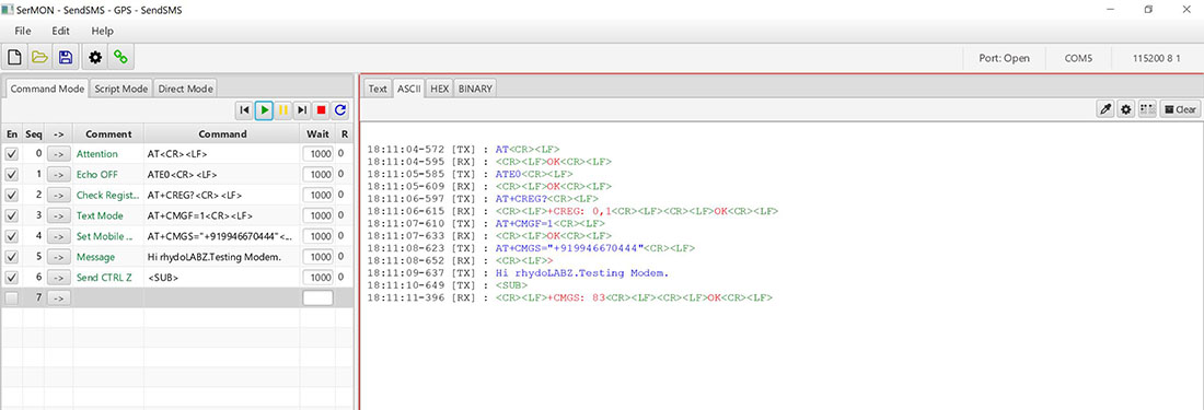
Sending SMS using USB From Computer
- Connect Modem to Computer using either on board USB Port or using External USB to Serial converter board.
-
Open Serial port software and enter the below command to send SMS.
-
AT<CR><LF>
Attention Command, this signifies that our Modem is working properly.
Answer Expected : OK -
ATE0<CR><LF>
This Command is being sent to stop the echo.
Answer Expected : OK -
AT+CREG?<CR><LF>
It is being used to check whether the SIM got registered with the Network.
Answer Expected : +CREG: 0,1 or +CREG: 0,5 -
AT+CMGF=1<CR><LF>
Configuring Text mode for sending SMS
Answer Expected : OK -
AT+CMGS="Mobile Number"<CR><LF>
Set the destination mobile number enclosed in the DOUBLE QUOTES.
Answer Expected : > -
"Hi, How are you?"<SUB>
Here we enter our message body followed by CONTROL-Z (<SUB>)
Answer Expected : SMS confirmation starting with "+CMGS"
-
-
SerialMonitor Software Command/Response View for Sending SMS.
Sending SMS using ARDUINO via UART
-
Arduino Code using Software Serial port download
1234567891011121314151617181920212223242526272829#include <SoftwareSerial.h>;SoftwareSerial mySerial(2, 3); // Assign pins for RX, TXvoid setup(){mySerial.begin(115200); // set the baud ratemySerial.print("AT\r\n"); // Transmit AT to the moduledelay(500); // wait for a 500ms delaymySerial.print("ATE0\r\n"); // Echo Offdelay(500); // wait for a 500ms delaymySerial.print("AT+CMGF=1\r\n"); // Switch to text modedelay(500); // wait for a 500ms delay}void loop(){mySerial.print("AT+CMGS=\"9349160503\"\r\n"); // Send SMS to a cell numberdelay(500); // wait for a 500ms delaymySerial.print("Test MSG");delay(500);mySerial.write(0X1A); // Ctrl-Z indicates end of SMSdelay(500); // wait for a 500ms delaywhile(1);}
-
Since Arduino UNO is sharing its serial port with USB IC via 1K Ohm series resistor , you may face difficulty to use normal serial port along with this modem. So above arduino codes are based on Software serial interface .
-
Arduino PIN 2 and PIN3 are used as RX and TX respectively for interfacing with Modem TX and RX.
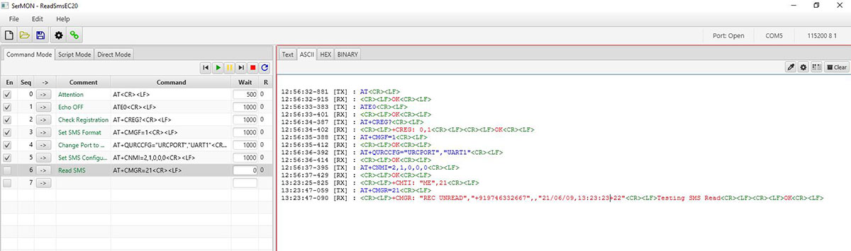
Reading SMS using Quectel EC20/EC25 4G LTE Modem
-
AT<CR><LF>
Attention Command, this signifies that our Modem is working properly.
Answer Expected : OK -
ATE0<CR><LF>
This Command is being sent to stop the echo.
Answer Expected : OK -
AT+CREG?<CR><LF>
It is being used to check whether the SIM got registered with the Network.
Answer Expected : +CREG: 0,1 or +CREG: 0,5 -
AT+CMGF=1<CR><LF>
Configuring Text mode for SMS
Answer Expected : OK -
AT+QURCCFG="URCPORT","UART1"<CR><LF>
For redirecting the modem replies to the UART1 Port as well. -
AT+CNMI=2,1,0,0,0<CR><LF>
Configure Modem to notify on incoming SMS reciept. Modem will inform the SMS reciept by "+CMTI:<Message index Number> " -
AT+CMGR=<Message index Number>
Now Read SMS using <Message index Number> received.
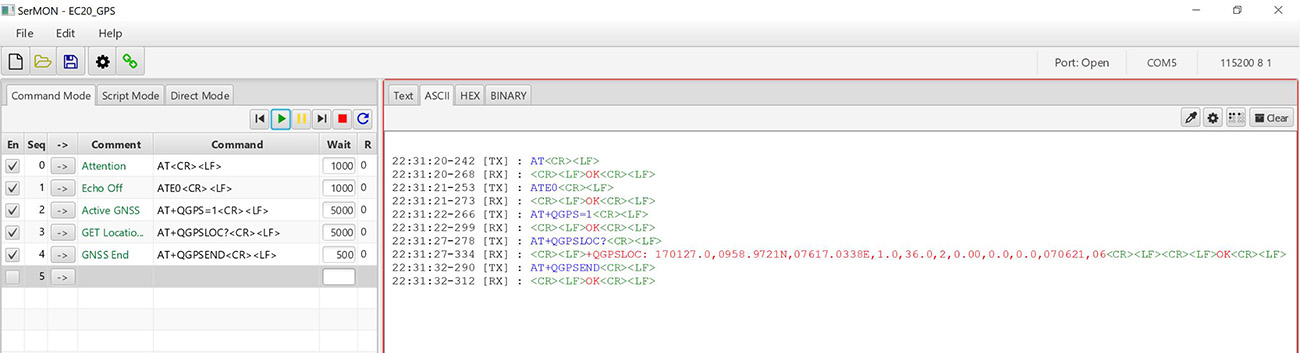
How to get GPS Location using Quectel EC20/EC25 4G LTE Modem
-
AT<CR><LF>
Attention Command, this signifies that our Modem is working properly.
Answer Expected : OK -
ATE0<CR><LF>
This Command is being sent to stop the echo.
Answer Expected : OK -
AT+QGPS=1<CR><LF>
Turn ON the GPS Function .
Answer Expected : OK -
AT+QGPSLOC?<CR><LF>
Initially we have to wait atleast 30 Seconds and issue this command to read the GPS location details
Answer Expected : GPS Data starting with "+QGPSLOC:" -
AT+QGPSEND<CR><LF>
Turn OFF the GPS Function before exiting.
Answer Expected : OK -
Leave a Reply
You must be logged in to post a comment.