GPS Receiver with Antenna -RS232 Serial/USB
It is a high gain GPS Receiver-RS232 made with ultra small High gain third generation POT (Patch Antenna On Top) GPS module. There is no prior configurations required , just apply power (9V) by DC adpater or to RMC Connector from a battery or USB , your data (NMEA 0183) is ready at TX pin.
 This is a stand alone GPS Module and requires no external components .It has a very compact and easy to integrate design with the ultimate tracking performances. It is also ideal for those who wishes to plug-and-play GPS receiver module into their small form factor design. It can be directly connected to PC through USB (No separate Power Required) or RS232 (COM Port), MAX232 level converter IC required to connect microcontroller/Arduino.
The GPS chipsets inside the module are designed by MediaTek Inc., which is the world’s leading digital media solution provider and largest fab-less IC company in Taiwan. The module can support up to 66 channels. The GPS solution enables small form factor devices. They deliver major advancements in GPS performances, accuracy, integration, computing power and flexibility. They are designed to simplify the embedded system integration process.
To determine the location of the GPS satellites two types of data are required by the GPS receiver: the almanac and the ephemeris. This data is continuously transmitted by the GPS satellites and your GPS receiver collects and stores this data.The data received is just ASCII text and varies in precision. Every sentence begins with a ‘$’ sign, has about 80 characters and ends up with a carriage return/line feed sequence. Sentences are mostly framed in single lines (may run over to multiple lines sometimes) and the data items in each sentence are separated by commas.As the module provides current time, date, latitude, longitude, speed, altitude and travel direction / heading among other data, so it can be used in a host of applications, including navigation, tracking systems, fleet management, mapping and robotics.
Features:

- MediaTek MT3329 Chipset, L1 Frequency, C/A code, 66 Channels
- RS232 Interface via DB9 Connector
- USB MiniB type connector for USB interface and Power
- 9 VDC supply @ 55 mA (typical)
- Data output Baud rate: 9600 bps(Default)
- Standard NMEA0183 output format
- Low Power Consumption: 55mA @ acquisition, 40mA @ tracking
- High Sensitivity, -165 dBm, TCXO Design , superior urban performances
- Position Accuracy: <3.0M 2D-RMS
- DGPS (WAAS/EGNOS/MASA/GAGAN) Support
- Multi-path Compensation ; E-GSM-900 Band Rejection
- Cold Start is Under 36 seconds (Typical)
- Warm Start is Under 34 seconds (Typical)
- Hot Start is Under 1 second (Typical)
- Max. Update Rate : 10Hz (Default: 1 Hz)
Specifications:


PIN Diagram:
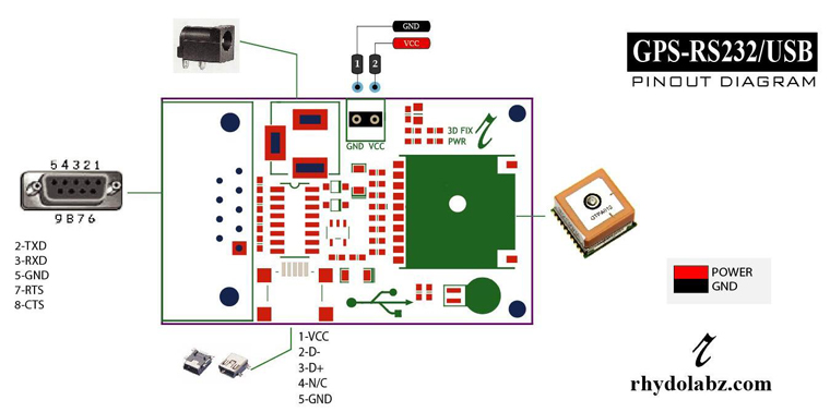
GPS -RS232 /USB PIN descriptions are as below


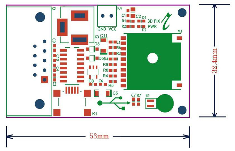
Layout:

How to Test:

1. Reading GPS data through RS232 port:
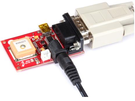
- Connect the GPS receiver to your PC using a RS232 DB9 cable. Normally Desktop systems might be having a DB9 RS232 port available,So you can directly connect the product to the system using that port, and appropriately power the module using the desired power source (9V),connection diagram is shown below.
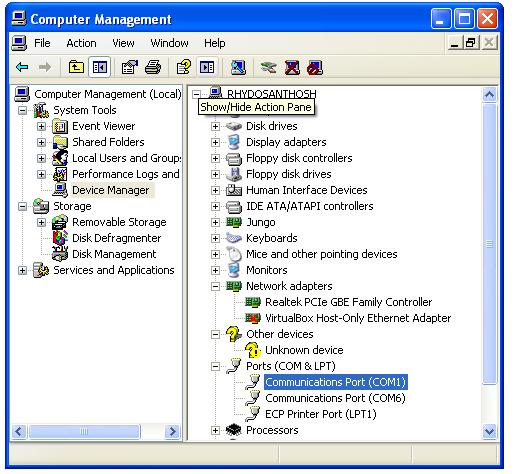
- Choose the appropriate COM port that got assigned to the RS232 DB9 serial cable in your system by looking into the device manager like shown below.
- By measuring distance from four satellites four spheres are drawn from earth to each satellite. Those spheres only intersect at only one earth point (your location). If there were only 3 satellites, there is more then one place the spheres intersect which is why the system needs that forth satellite so a bad calculation can not be made. The GPS receiver needs 4 satellites to work out your position in 3-dimensions. In GPS Receiver-RS232/USB “3D LED”(Yellow) is blinks in every fraction of seconds to indicate weak signal from satellites. When the GPS receiver gets stronger signal the “3D LED” is turned off. The GPS receiver will send raw GPS data based on NMEA 0183 protocol to the PC.
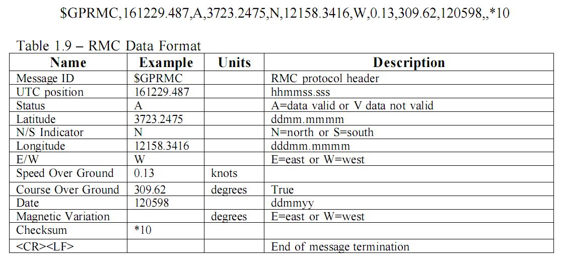
- Here sample test was done using GPRMC header . GPRMC tells the latitude, longitude, speed, time and date. The details of GPRMC message is shown below.
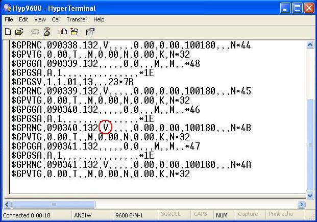
- When GPS receiver get the weak signal,then the received GPS data is as shown in the figure.The data ‘V’ on the GPRMC header indicate a weak signal from the satellite and GPS Receiver-RS232/USB “3D LED”(Yellow) will blinks in every fraction of seconds.
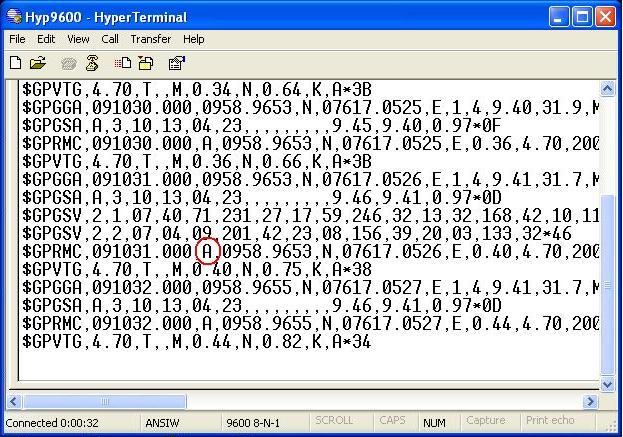
- When the GPS receiver gets stronger signal from satellite the “3D LED” is turned off,the GPS data received is as shown in the figure.The data ‘A’ on the GPRMC header indicate the strong signal from the satellite.
2. Reading GPS data through USB port:
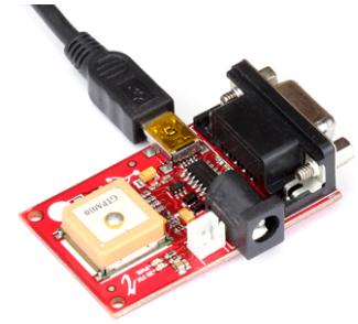
- When making connection from a Laptop or PC using the USB port, no need to give any external power as the power for the Device operation shall be derived from the USB itself. When working out through USB no other connection from the device is required,connection diagram is shown below.
- The first thing you want to do is installing the GPS Receiver-RS232/USB VCP driver (Virtual Com Port driver) for your PC because Virtual COM port (VCP) makes USB communication with GPS Module .The chip on the board translates the serial data coming from a device into USB data and vice-versa. For a quick tutorial on How to install USB driver for rhydoLABZ GPS Receiver-RS232/USB please Go through the link.
- Once you are done with all these procedures , Choose the appropriate COM port that got assigned to the USB in your system by looking into the device manager like shown below you can see USB serial COM3 got selected:
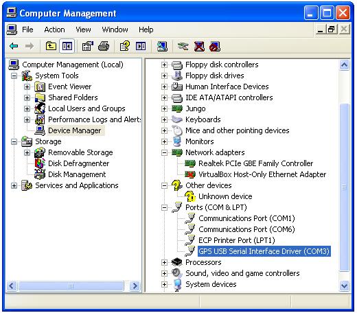
- You can check the GPS data With the help of Hyperterminal ,rhydoLABZ Tracking Software or Mini GPS Tool.
3. Test your GPS Receiver-RS232/USB with rhydoLABZ Tracking Software
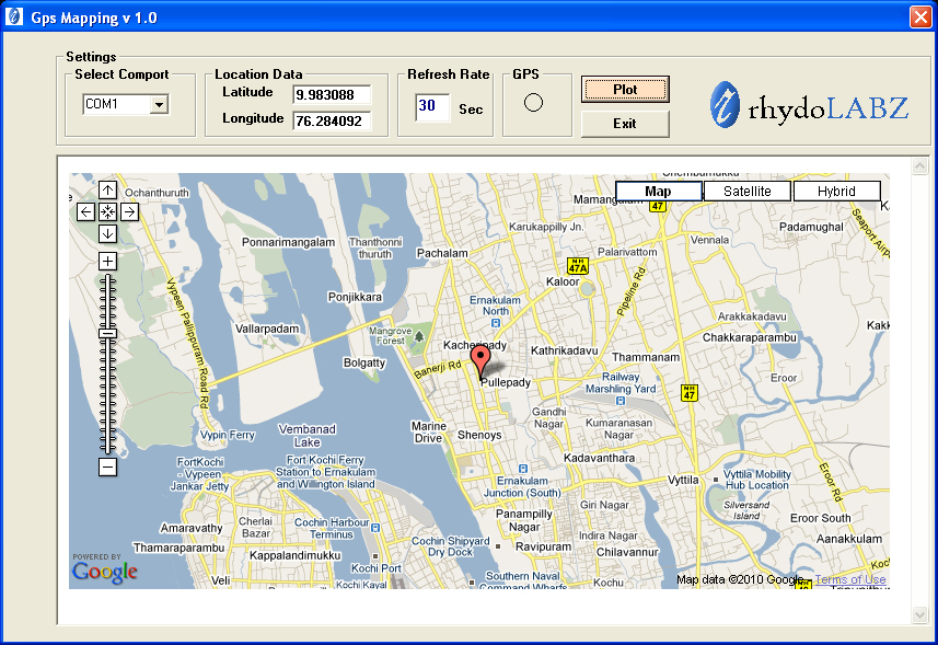
- With the help of Hyper terminal or any other terminal software, you will only be able to see the full NMEA protocol coming in ASCII format and rhydoLABZ tracking software plot your location with the help of GOOGLE map.For using the rhydoLABZ software you need to have net connectivity.
- Install the rhydoLABZ Tracking Software (Windows) in your PC shown below.
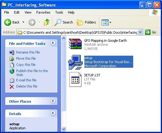
- Open rhydoLABZ Tracking software ,select appropriate COM port from “Select Comport “. The Latitude and Longitude details of the device will be shown in the rhydoLABZ Tracking software,you can get the map view of your location by simply clicking “plot”.
4. Test your GPS Receiver-RS232 Serial/USB with Arduino
- When interfacing GPS Receiver-RS232 Serial/USB with Arduino need level shifter (max232 ic)because microcontroller and GPS Receiver-RS232 Serial/USB are different logic levels,connection diagram is shown below.

- Program is shown below.
|
1 2 3 4 5 6 7 8 9 10 11 12 13 14 15 16 17 18 19 20 21 22 23 24 25 26 27 28 29 30 31 32 33 34 35 36 37 38 39 40 41 42 43 44 45 46 47 48 49 50 51 52 53 54 55 56 57 58 59 60 61 62 63 64 65 66 67 68 69 70 71 72 73 74 75 76 77 78 79 80 81 82 83 84 85 86 87 88 89 90 91 92 93 |
/************************************************************************************** Program to read GPS data and print data to serial monitor. BOARD : Arduino Duemilanove Shield : Arduino XBee Shield from Rhydo Labz (Part No : RD-2069) **************************************************************************************/ int Gpsdata; // for incoming serial data unsigned int finish =0; // indicate end of message unsigned int pos_cnt=0; // position counter unsigned int lat_cnt=0; // latitude data counter unsigned int log_cnt=0; // longitude data counter unsigned int flg =0; // GPS flag unsigned int com_cnt=0; // comma counter char lat[20]; // latitude array char lg[20]; // longitude array void Receive_GPS_Data(); /************************************************************************************** Function : setup() Description : Use it to initialize variables, pin modes, start using libraries, etc. The setup function will only run once, after each power up or reset of the Arduino board. **************************************************************************************/ void setup() { Serial.begin(9600); // opens serial port, sets data rate to 9600 bps } /************************************************************************************ Function : loop() Description : loops consecutively, allowing your program to change and respond. Use it to actively control the Arduino board. ************************************************************************************/ void loop() { Receive_GPS_Data(); Serial.print("Latitude : "); Serial.println(lat); Serial.print("Longitude : "); Serial.println(lg); finish = 0;pos_cnt = 0; } /************************************************************************************ Function : Receive_GPS_Data() Description : finding Latitudse and longitude from GPRMC message ************************************************************************************/ void Receive_GPS_Data() { while(finish==0){ while(Serial.available()>0){ // Check GPS data Gpsdata = Serial.read(); flg = 1; if( Gpsdata=='$' && pos_cnt == 0) // finding GPRMC header pos_cnt=1; if( Gpsdata=='G' && pos_cnt == 1) pos_cnt=2; if( Gpsdata=='P' && pos_cnt == 2) pos_cnt=3; if( Gpsdata=='R' && pos_cnt == 3) pos_cnt=4; if( Gpsdata=='M' && pos_cnt == 4) pos_cnt=5; if( Gpsdata=='C' && pos_cnt==5 ) pos_cnt=6; if(pos_cnt==6 && Gpsdata ==','){ // count commas in message com_cnt++; flg=0; } if(com_cnt==3 && flg==1){ lat[lat_cnt++] = Gpsdata; // latitude flg=0; } if(com_cnt==5 && flg==1){ lg[log_cnt++] = Gpsdata; // Longitude flg=0; } if( Gpsdata == '*' && com_cnt >= 5){ com_cnt = 0; // end of GPRMC message lat_cnt = 0; log_cnt = 0; flg = 0; finish = 1; } } } } |
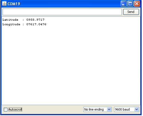
- When Arduino board received GPS data,the data printed on serial monitor is as shown in the figure.
5. Test your GPS GPS Receiver-RS232 Serial/USB with PIC 16F877A
- When interfacing GPS Receiver-RS232 Serial/USB with PIC 16F877A need level shifter (max232 ic)because microcontroller and GPS Receiver RS232 Serial/USB are different logic levels,connection diagram is shown below.
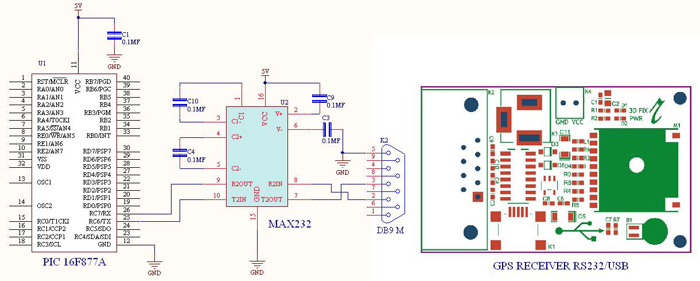
- Program is shown below.
123456789101112131415161718192021222324252627282930313233343536373839404142434445464748495051525354555657585960616263646566676869707172737475767778798081828384858687888990919293949596979899100101102103104105106107108109110111112113114115116117118119120121122123124125126127128129130/*****************************************************************************Microcontroller -- PIC 16 F877A - 40-pin-8-bit.Clock Frequency is 20 MHz -- Period in 200 Nano secondbaudrate-9600.Only the output message – $GPRMC (Recommended minimum specificGNSS data) is read. The latitude and Longitude value is displayed in the Serialmonitor.*****************************************************************************/#include<pic.h>/*****************************************************************************GLOBAL VARIABLES*****************************************************************************/unsigned char Gpsdata; // for incoming serial dataunsigned int finish =0; // indicate end of messageunsigned int pos_cnt=0; // position counterunsigned int lat_cnt=0; // latitude data counterunsigned int log_cnt=0; // longitude data counterunsigned int flg =0; // GPS flagunsigned int com_cnt=0; // comma counterunsigned char lat[20]; // latitude arrayunsigned char lg[20]; // longitude array/*****************************************************************************FUNCTION DEFINITIONS*****************************************************************************/void UART_Initilization();void UART_String(const unsigned char *dat);void main(){TRISC = 0X80;UART_Initilization(); // uart InitializationGIE = 1; // Globel interrupt enable bitPEIE = 1; // Peripheral interrupt enable bitwhile(1){while(finish!=1);UART_String("Latitude : "); // printing GPS data to serial monitorUART_String(lat);UART_String("\r\n");UART_String("Longitude : ");UART_String(lg);UART_String("\r\n");finish = 0;pos_cnt = 0;}}/*****************************************************************************Function : interrupt ISR()Description : interrupt service*****************************************************************************/void interrupt ISR(){if(RCIF){RCIF = 0;Gpsdata = RCREG;flg = 1;if(finish == 0){if( Gpsdata=='$' && pos_cnt == 0) // finding GPRMC headerpos_cnt=1;if( Gpsdata=='G' && pos_cnt == 1)pos_cnt=2;if( Gpsdata=='P' && pos_cnt == 2)pos_cnt=3;if( Gpsdata=='R' && pos_cnt == 3)pos_cnt=4;if( Gpsdata=='M' && pos_cnt == 4)pos_cnt=5;if(Gpsdata=='C' && pos_cnt == 5 )pos_cnt=6;if(pos_cnt==6 && Gpsdata ==','){ // count commas in messagecom_cnt++;flg=0;}if(com_cnt==3 && flg==1){lat[lat_cnt++] = Gpsdata; // latitudeflg=0;}if(com_cnt==5 && flg==1){lg[log_cnt++] = Gpsdata; // longitudeflg=0;}if( Gpsdata == '*' && com_cnt >= 5 && flg == 1){lat[lat_cnt] ='\0'; // end of GPRMC messagelg[log_cnt] = '\0';lat_cnt = 0;log_cnt = 0;flg = 0;finish = 1;com_cnt = 0;}}}}/****************************************************************************Function : USART_InitilizationDescription : uart basic initilizatin*****************************************************************************/void UART_Initilization(){TXEN = 1;SYNC = 0;BRGH = 1;SPBRG = 0X81;SPEN = 1;CREN = 1;RCIE = 1;RCIF = 0;}/*****************************************************************************Function : USART_StringDescription : transmiting string of datas****************************************************************************/void UART_String(const unsigned char *dat){while(*dat!='\0'){TXREG = *dat;while(TRMT!=1);dat++;}}
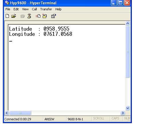
- When PIC16F877A received GPS data,the data printed on serial monitor is as shown in the figure.
Resources:
 Schematic
Mini GPS User Manual
Mini GPS Tool
rhydoLABZ Tracking Software (Windows)
How to Buy: Click here to buy GPS Receiver with Antenna-RS232 Serial/USB
Support: Please share your ideas with us, visit our forum for discussion.
Frequently Asked Questions(FAQ): Q. Where do we mount GPS?
Ans. GPS data available around the world. The GPS receiver will need to have a clear View of sky so that the GPS receiver can triangulate at least three satellites. We may find problem receiving signals in indoor area. The GPS signal may blocked by metal, deep forest, mountains etc.
Q. Do we need net connection to work GPS?
Ans. No. we don’t need internet connection for GPS data reception.
Q.Do we need net connection to work GPS Receiver-RS232/USB with rhydoLABZ Software.
Ans. Yes we need net net connection to work with rhydoLabz Software.
Q . Is GPS Receiver-RS232/USB need external antenna?
Ans. No, the module is made with ultra small High gain third generation POT (Patch Antenna On Top) GPS module.
Q.Is GPS Receiver-RS232/USB require external power?
Ans. Reading GPS data through RS232 port requires external power.When we connect GPS Receiver-RS232/USB through USB requires no external power,Power is taken from USB port itself.

Leave a Reply
You must be logged in to post a comment.