LPG Gas Sensor Module
RhydoLabz’s LPG Gas Sensor Module is designed to detect the presence of a dangerous LPG leak in your Home, car or in a service station, storage tank environment by interfacing with Microcontroller without ADC Channels and programming. In this version of LPG Gas sensor module two pots are included, one for trigger level setting and the other for setting sensitivity of the sensor. It allows to determine when a preset LPG gas level has been reached or exceeded. The module uses MQ-6 sensor to sense LPG leak. The MQ-6 can detect gas concentrations anywhere from 200 to 10000 ppm.
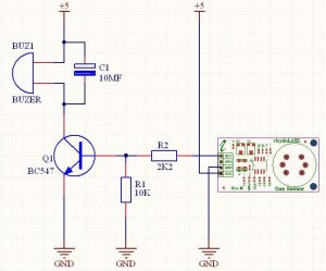
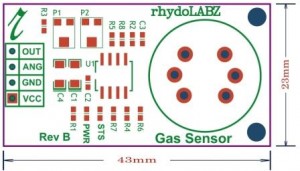
Interfacing with the sensor module is done through a 4-pin breadboard compatible SIP header and requires One I/O pin from the host microcontroller. The onboard microcontroller provide initial heating interval after power-up and then starts to measure LPG sensor output.If it found the LPG concentration above preset value , it will inform the Host controller by pulling the Output Pin to High and Starts to blink a onboard status LED. The sensor module is mainly intended to provide a means of comparing LPG sources and being able to set an alarm limit when the source becomes excessive.
The best location to fix Gas Sensor Module is near the Gas Cylinder or near the pipeline in case of piped gas connection. In case of LPG, when Gas leakage occurs , the gas will settle down near the floor because LPG is heavier than the air. So for best results it would be advisable to fit Gas Sensor Module nearly 1m above the floor.
Features:
- Uses the MQ-6 LPG Gas Sensor
- Easy SIP interface
- Compatible with most microcontrollers
- Analog Sensor voltage is available at ANG pin.
- Onboard Status and Power LED
- Onboard Pot for threshold setting
- Onboard Pot for Sensitivity setting
- On board microcontroller


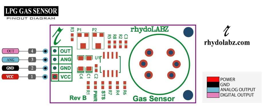 Pin details of LPG Gas Sensor Module -V2 is as given below.
 NOTE: 1. A high on OUT pin indicates LPG presence. This pin can be connected to the Digital I/O pin of the microcontroller.
- There are two potentiometers used in Gas Sensor Module . they are as follows:
- POT P1: The on-board POT P1 is used to set tolerance voltage for detecting the LPG presence. When LPG is detected, the OUT pin will be high. This will occurs when the output voltage is greater than the tolerance level set, using the POT P1.
- POT P2: The on-board POT P2 is used to set the sensitivity of the Gas sensor. We recommend you to calibrate the detector for 1000ppm of LPG concentration in air and use value of POT P2 about 20KΩ.
- There are two leds in Gas Sensor Module . They are:
- D1: PWR Led. This Green Led indicates the Power input.
- D2: STS Led.The red status Led (STS) indicates the various status of LPG Sensor module eg. Power on, initialization & LPG detection. When the sensor is powered up, the STS led will blink twice to indicate the module is functional. There after STS Led will blinks every second till the module is getting ready ( Heating Zone) . After the sensor is initialized, the module will enter in to the ARM mode and ready to detect the gas concentration , during this period the STS led will blink in step of 3 seconds. When LPG is detected, the STS led will blink fast till the level goes below the set threshold.

- Place the gas sensor module in a clean environment.
- Before powering up the module , first you need to set the sensitivity. According to the manufacture specification it is recommended to set the sensitivity to approximately 20k(by varying potentiometer P2) . In order to view the value ,place the multimeter probe to the ANG pin and the other end to the GND .
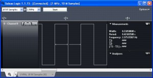
- Once the sensitivity adjustment has been done, power up the module with 5v. At the first stage you can observe the STS(STATUS) led blinking twice i.e, in order to indicate the module is functioning. Below shows the STS led waveform.
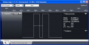
- LPG gas sensor module enters into 3 zones
- Heating zone
- Armed zone
- Trigger or sensing zone
1.Heating Zone
Module enters to heating zone after the power up. It takes around 2.30 minutes for the device to gets heated up. Adjust the potentiometer P1 to around 1V threshold (in order to note down the threshold voltage, check across the 6th pin of IC using multimeter ).Once the module enters the heating zone ,STS led blinks once in a second and wave form is shown below: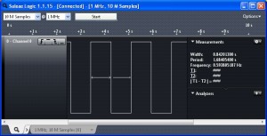 2.Armed zone
Module once after the heating zone, enters into the armed zone. This is the stage before the gas sensing zone. If the led blinks once in 4 second, it means there is no presence of gas and also indicates that calibration has been done successfully . After this stage Module enters to the Trigger or sensing Zone and STS led waveform is shown below.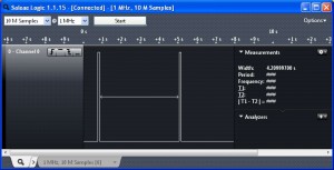
3.Trigger or sensing Zone
Here the module enters to the gas sensing zone. If the module detects the GAS ,ie when the GAS concentration increases STS led will start blinking rapidly and will take around 250 msec ON time and same as OFF time. Fast blinking of LED indicates the presence of gas. When the gas concentration decreases, led will start blinking once in 4 seconds indicates absence of gas and STS led waveform is shown below.
Analog value > threshold value – STS led blinks faster
Analog value < threshold value – STS led blinks slower

|
1 2 3 4 5 6 7 8 9 10 11 12 13 14 15 16 17 18 19 20 21 22 23 24 25 26 27 28 29 30 31 32 33 34 35 36 37 38 39 40 41 42 43 44 45 46 47 48 49 50 51 52 53 54 55 56 57 58 59 60 61 62 63 64 65 66 67 68 69 70 71 72 73 74 75 76 77 78 79 80 81 82 83 84 85 86 87 88 89 90 91 92 93 94 95 96 97 98 99 100 101 102 103 104 105 106 107 108 109 110 111 112 113 114 115 116 117 118 119 120 121 122 123 124 125 126 127 128 |
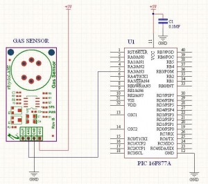
/******************************************************************************** * Microcontroller -- PIC 16 F877 - 40-pin - 8-bit * * Clock Frequency is 20 MHz -- Period in 200 Nano Seconds * * USART - BaudRate 9600 * * This program is used to read gas sensor value *********************************************************************************/ #include<pic.h> #include"delay.c" int LPG_Value=0; void ADC_init() ; void send(char); int adc_conv(int); void SerialPortInit() ; void SendData(char); void display(int value ); void MSdelay(unsigned int); static void Send2USART(const char *CPtr1); void main() { TRISC=0X80; TRISA=0XFF; SerialPortInit() ; ADC_init(); while(1) { Send2USART("LPG Value:"); // send LPG value LPG_Value=adc_conv(1); // select channel 1 for LPG reading display(LPG_Value ); // convert LPG value for display SendData('\n'); // new line SendData('\r'); // carriage return } } /***************************************************************************** * Function : Send2USART * Description : Group of data send serially ******************************************************************************/ static void Send2USART(const char *Cptr1) { while(*Cptr1 != '\0') { SendData(*Cptr1); Cptr1++; } } /***************************************************************************** * Function : display * Description : Display adc value function ******************************************************************************/ void display(int value ) { char k=1; char array[4]; for(k=1;k<=4;k++) { array[k]=value%10; value=value/10; } for(k=4;k>=1;k--) { SendData(array[k]+'0'); } } /***************************************************************************** * Function : SerialPortInit * Description : Usart Initialization function - Baud Rate 9600 ******************************************************************************/ void SerialPortInit() { GIE=1; SYNC=0; TXEN=1; BRGH=1; SPEN=1; CREN=1; PEIE=1; RCIE=1; SPBRG=129; } /***************************************************************************** * Function : ADC_init * Description : Adc Initialization function ******************************************************************************/ void ADC_init() { ADFM=1; PCFG3=0; PCFG2=0; PCFG1=0; PCFG0=0; } /***************************************************************************** * Function : adc_conv * Description : Adc Conversion function ******************************************************************************/ int adc_conv(int channel) { int ab; ADCON0=0x81|channel<<3; //channel selection DelayMs(1); ADGO=1; //start AD conversion while(ADGO!=0); //waiting for competion of AD conversion ab=ADRESH; //assign 2bit value ADRSH register to variable ab ab=ADRESH<<8; //8 times shift variable ab value ab=ab|ADRESL; //combine ADRESL & ab value return(ab); } /***************************************************************************** * Function : SendData * Description : Send a data serially ******************************************************************************/ void SendData(char sdata) { TXREG=sdata; while(TRMT!=1); } /***************************************************************************** * Function : MSdelay * Description : Generate 1ms delay ******************************************************************************/ void MSdelay(unsigned int val) { unsigned int del,del1; for(del=1;del<=val;del++) { for(del1=0;del1<=331;del1++); } } |
Upload the example code in PIC and connect LPG sensor module with PIC 16F877A . Then open serial monitor, LPG sensor will give values as shown below. When LPG sensor module detects gas, the value will change.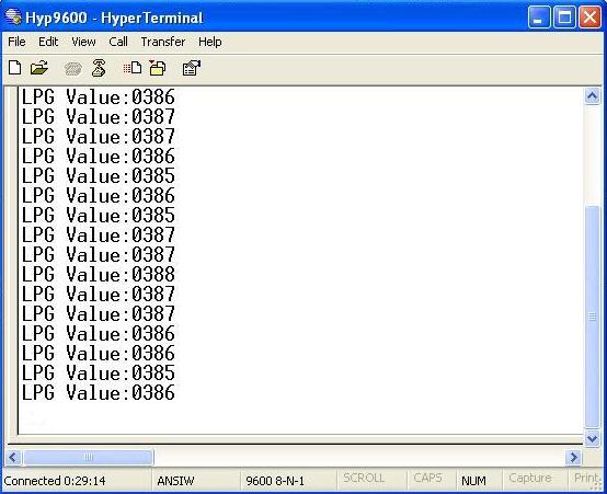


Leave a Reply
You must be logged in to post a comment.