Interfacing a GPS Shield with Arduino
Shields are boards that can be plugged on top of the Arduino PCB extending its capabilities. The purpose of a shield is to provide new plug-and-play functionality to the host micro controller, such as circuit prototyping, motion control, sensor integration, network and radio communication, or gaming interfaces, without worrying too much about the hardware implementation details. The different shields follow the same philosophy as the original toolkit: they are easy to mount.
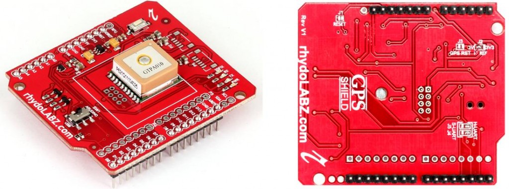 With GPS Shield populated with GPS module you can add GPS functionality to your Arduino or you can receive the NMEA(0183) data on your PC/Laptop with a easiness of sliding a switch. GPS shields are mostly based on the latest Arduino R3 Layout with additional pins and is compatible to latest Arduino DUE which requires 3V3 as well as all other Arduinos and clones at 5V. There is a board level converter for this purpose Level conversion is achieved by 3 state buffer IC and MOSFET Level converter instead of normal Resistive voltage dividers.
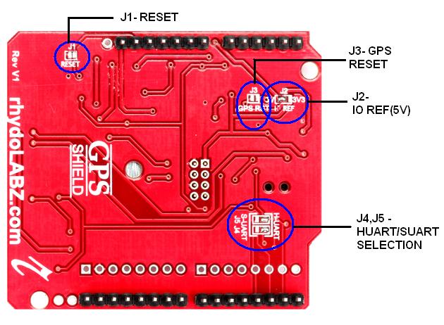
1. Jumpers:
- j1 – On-board PCB jumper j1 is connected between Arduino’s reset pin and ground,that is across reset switch. whenever you are using a board with controller IC it will make the Rx pin high,this may cause error in received data so in such case you have to press that reset switch or remove that IC from the board and receive the accurate data in window terminal.In some cases the IC is directly embedded on the board in such cases j1 is connected to make communication with PC possible.
- j2– Power to the GPS module is taken from Arduino board through 3V3 LDO Voltage Regulator. Jumper J2 is used for the selection of VREF. If 5V-only Arduino board is used, 5V to 3.3V conversion is necessary. It is usually done with LDO; basically all you need is a level shifter. So the 5V power selector jumper j2 closed, 3.3V jumper open, VBUS powered from 5V, input of LDO connected to VBUS pad and output of LDO connected to 3.3V pad on the circuit side of 3.3V jumper.
- j3 – GPS Reset. The jumper j3 is used to reset the GPS using software.This jumper is connected between Arduino’s pin D4 and reset pin through npn transistor Q2. we can program to make D4 high, when j3 is connected, the Q2 base is also high.This will make Q2 ON and reset connected to ground.
- j4 & j5– On-board PCB jumpers J4 & J5 are provided at the bottom of PCB to select the Rx and Tx pin of Digital UART or Software UART on Arduino. The jumper position in the figure shows the default condition that is selection of digital UART .
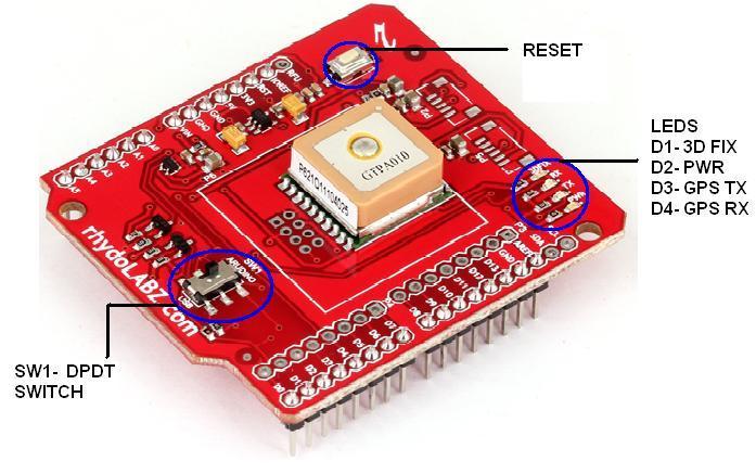
2. DPDT switch(SW1): The DPDT switch(SW1) switches the GPS module’s input/output between Arduino’s and USB Transceiver so as to get NMEA data on PC via USB connector or on Arduino board.This feature help you to verify the GPS data and test its functionality before doing and coding on Arduino.
3. RESET switch:The Arduino reset switch is also brought out at the PCB for your easy access.RESET switch is directly connected to the Arduino reset switch.This switch is used to restart the Arduino sketch.
4. LEDs : The GPS-shield also includes LEDs to indicate power and activity on RXD,TXD, 3D Fix pins.
- D1 (3D FIX ): In the board “3D FIX LED”(Yellow) blinks in every fraction of seconds to indicate weak signal from satellites. When the GPS receiver gets stronger signal, the “3D FIX LED” is turned off.
- D2 (PWR): A blue led is used for power indication.
- D3(TX) : When “3D FIX LED” is turned off,the GPS receiver will send raw GPS data based on NMEA 0183 protocol to the PC.This is indicated by the Red led in the TXD pin.
- D4(RX): A green led is connected to the RXD pin to indicate the data reception.
 The shield does come with headers installed, So no Soldering required at all.
GPS Shield with GPS -A6B Features:
- Compatible with all Arduinos including latest Arduino Due
- On board A6B GPS Receiver
- Can be use as GPS development board
- Mounts directly onto your Arduinos
- Selectable level Shifting (5V & 3V3)
- 3.3V power regulation and level shifting on-board
- Reset button brought out
- Power, RXD, TXD, 3DFix indicator LED s
- EM-406 Footprint and Filter caps on board
- EM-408 Footprint and Filter caps on board
- EB-85A Footprint and Filter caps on board
- Arduino R3 sized shield – Suitable for present and future Arduinos as well.
- Arduino reset button
- DPDT switch controls the GPS Connectivity either to Arduino or to USB
Compatible with:
- Arduino Deumlanove/UNO
- Arduino Due
- Arduino MEGA
- Leaf maple
- ChipKit MAX32
- ChipKit UNO32
- FEZ Panda II
- Freeduino
- Simple Cortex
- Seeeduino
- Seeeduino MEGA
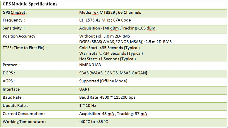
Specifications:
PIN Diagram:
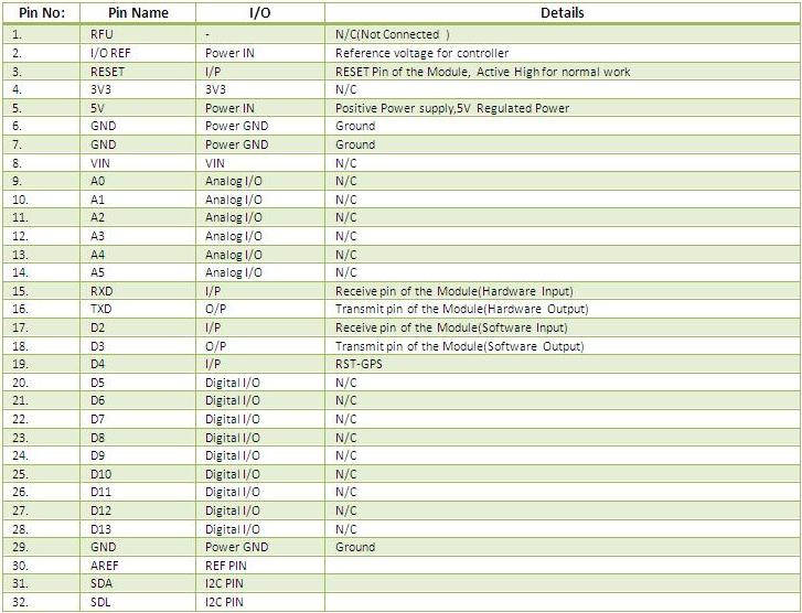
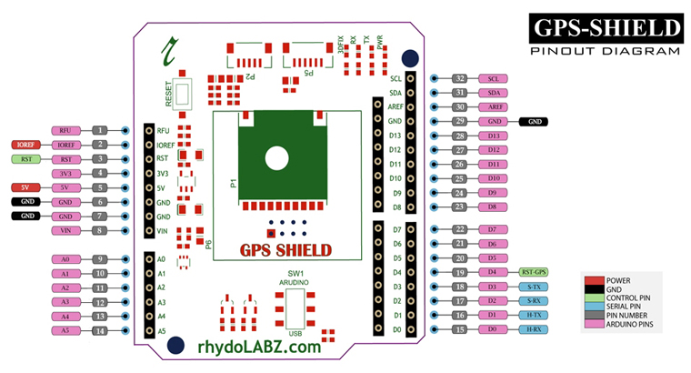 GPS Shield with GPS- A6B PIN descriptions are as below
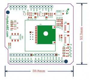
Layout:
How to test:
1. USB mode – Without micro controller IC on arduino board
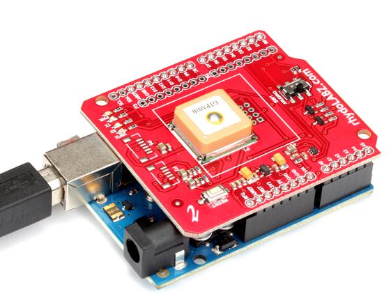
- Here one sample test is shown using GPS Shield with GPS- A6B
- Place the GPS Shield on the arduino board.
- Switch the DPDT switch in USB mode.
- If the GPS receiver is new, or has not been used for some time, it may need 15 minutes or so to receive a current almanac.
- Open the serial terminal
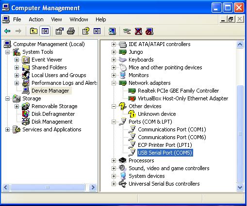
- Choose the appropriate COM port that got assigned to the explorer in your system by looking into the device manager like as shown below.In this figure you can see USB serial COM5 got selected:
- By measuring distance from four satellites four spheres are drawn from earth to each satellite. Those spheres only intersect at only one earth point (your location). If there were only 3 satellites, there is more then one place the spheres intersect which is why the system needs that forth satellite so a bad calculation can not be made. The GPS receiver needs 4 satellites to work out your position in 3-dimensions. The GPS receiver will send raw GPS data based on NMEA 0183 protocol to the PC.
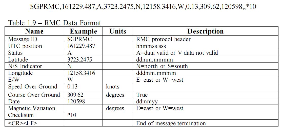
- Here sample test was done using GPRMC header . GPRMC tells the latitude, longitude, speed, time and date. The details of GPRMC message is shown below
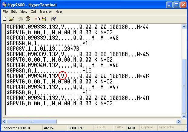
- When GPS receiver receives a weak signal,then the received GPS data is as shown in the figure. The data ‘V’ on the GPRMC header indicate a weak signal from the satellite.
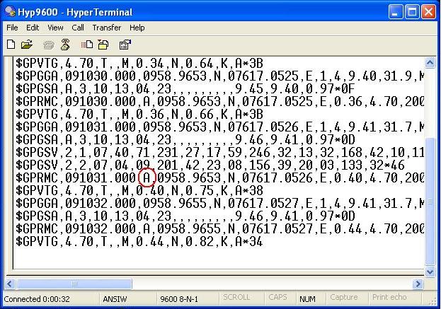
- When the GPS receiver gets stronger signal from satellite,the GPS data received is as shown in the figure. The data ‘A’ on the GPRMC header indicate the strong signal from the satellite.
2. Arduino mode – With micro controller IC on arduino board
- While testing in Arduino mode, the switch on the GPS shield should be in Arduino mode Program is shown below
|
1 2 3 4 5 6 7 8 9 10 11 12 13 14 15 16 17 18 19 20 21 22 23 24 25 26 27 28 29 30 31 32 33 34 35 36 37 38 39 40 41 42 43 44 45 46 47 48 49 50 51 52 53 54 55 56 57 58 59 60 61 62 63 64 65 66 67 68 69 70 71 72 73 74 75 76 77 78 79 80 81 82 83 84 85 86 87 88 89 90 91 92 93 |
/************************************************************************************** Program to read GPS data and print data to serial monitor. BOARD : Arduino Duemilanove Shield : Arduino GPS Shield from Rhydo Labz (Part No :ARD-2116) **************************************************************************************/ int Gpsdata; // for incoming serial data unsigned int finish =0; // indicate end of message unsigned int pos_cnt=0; // position counter unsigned int lat_cnt=0; // latitude data counter unsigned int log_cnt=0; // longitude data counter unsigned int flg =0; // GPS flag unsigned int com_cnt=0; // comma counter char lat[20]; // latitude array char lg[20]; // longitude array void Receive_GPS_Data(); /************************************************************************************** Function : setup() Description : Use it to initialize variables, pin modes, start using libraries, etc. The setup function will only run once, after each power up or reset of the Arduino board. **************************************************************************************/ void setup() { Serial.begin(9600); // opens serial port, sets data rate to 9600 bps } /************************************************************************************ Function : loop() Description : loops consecutively, allowing your program to change and respond. Use it to actively control the Arduino board. ************************************************************************************/ void loop() { Receive_GPS_Data(); Serial.print("Latitude : "); Serial.println(lat); Serial.print("Longitude : "); Serial.println(lg); finish = 0;pos_cnt = 0; } /************************************************************************************ Function : Receive_GPS_Data() Description : finding Latitudse and longitude from GPRMC message ************************************************************************************/ void Receive_GPS_Data() { while(finish==0){ while(Serial.available()>0){ // Check GPS data Gpsdata = Serial.read(); flg = 1; if( Gpsdata=='$' && pos_cnt == 0) // finding GPRMC header pos_cnt=1; if( Gpsdata=='G' && pos_cnt == 1) pos_cnt=2; if( Gpsdata=='P' && pos_cnt == 2) pos_cnt=3; if( Gpsdata=='R' && pos_cnt == 3) pos_cnt=4; if( Gpsdata=='M' && pos_cnt == 4) pos_cnt=5; if( Gpsdata=='C' && pos_cnt==5 ) pos_cnt=6; if(pos_cnt==6 && Gpsdata ==','){ // count commas in message com_cnt++; flg=0; } if(com_cnt==3 && flg==1){ lat[lat_cnt++] = Gpsdata; // latitude flg=0; } if(com_cnt==5 && flg==1){ lg[log_cnt++] = Gpsdata; // Longitude flg=0; } if( Gpsdata == '*' && com_cnt >= 5){ com_cnt = 0; // end of GPRMC message lat_cnt = 0; log_cnt = 0; flg = 0; finish = 1; } } } } |
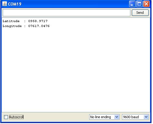
- When Arduino board receives GPS data,the data on serial monitor is as shown in the figure.
3. Test GPS shield with rhydoLABZ Tracking Software
With the help of Hyper terminal or any other terminal software, you will only be able to see the full NMEA 0183 protocol coming in ASCII format and rhydoLABZ tracking software plot your location with the help of GOOGLE map. For using the rhydoLABZ software you need to have net connectivity.
- Here one sample test is shown using RhydoLabz GPS Shield
- Install the rhydoLABZ Tracking Software (Windows) in your PC shown below.
![]()
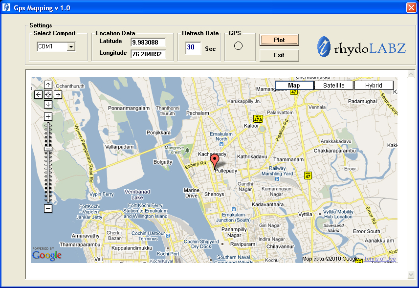
- Open rhydoLABZ Tracking software ,select appropriate COM port from “Select Comport “. The Latitude and Longitude details of the device will be shown in the rhydoLABZ Tracking software,you can get the map view of your location by simply clicking “plot”.
Resources: Schematic
Mini GPS User Manual
Mini GPS Tool
rhydoLABZ Tracking Software (Windows)
How to Buy: Click here to buy GPS Shield with GPS- A6B
Support: Please share your ideas with us, visit our forum for discussion.
Frequently Asked Questions(FAQ): Q. Where do we mount GPS shield?
Ans. GPS data available around the world. GPS shield is mounted on top of the Arduino. The GPS receiver will need to have a clear View of sky so that the GPS receiver can triangulate at least three satellites. We may find problem receiving signals in indoor area. The GPS signal may blocked by metal, deep forest, mountains etc.
Q.Do we need net connection to work GPS shield with rhydoLABZ Software.
Ans. Yes we need net connection to work with rhydoLabz Software.
Q. Do we need net connection to work GPS?
Ans. No. we don’t need internet connection for GPS data reception.
Q. What is NMEA 0183 ?
Ans. National Marine Electronics Association (NMEA) 0183 is a combined electrical and data specification for communication between marine electronic devices such as sonars GPS receivers etc and is controlled by, the U.S.-based National Marine Electronics Association.
Q. What is almanac ?
Ans. The GPS almanac is a set of data that every GPS satellite transmits. Almanac data includes a set of parameters for each GPS satellite that can be used to calculate its approximate location in orbit.

Leave a Reply
You must be logged in to post a comment.