PIC QuickStart Board v2
The All New Revised QSB (QuickStart Board) for PIC16F877A is a Low Cost Development Board that can be used to quickly evaluate and demonstrate the capabilities of 40 PIN PIC microcontrollers like PIC16F877A/PIC16F887 microcontrollers. The board is designed to work as a header board with access to all pins for external connection. Ideally suitable for fast and easy development purposes at low cost
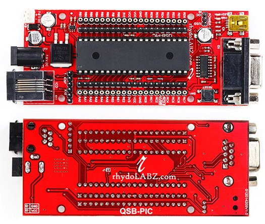
QSB PIC16F877A v2 Board Features
- Compact and Ready to use design
- Includes PIC16F877A Microcontroller
- Board Supports most of the 40pin PIC like PIC18F4580/4520/4550* Microcontrollers
- No separate Programmer required (Built in Bootloader)
- No Separate Power adapter required (USB powered)
- RS-232 Interface (For direct connection to PC’s serial port)
- All Port Pins available at Male Berg Strip and at female Berg housing connector
- On Board ICD Connector for Debugging ( Both RJ11 and 6PIN ICSP)
- Power Supply range of 7V to 20V
- On Board Power LED Indicator
- On Board Reset button
- On Board Port Pin LED connection for Board checking ( Jumper Selectable)
- On Board 20 MHz Crystal Oscillator
- Option to add external Crystals
- Can be used as header board for developing applications
- Power Supply Reverse Polarity Protection
- On Board 5V,1Amp Voltage Regulator
- On board 3V3 Voltage regulator IC and 3V3 available on Berg pins
- RMC connecter & DC Barrel Jack for External power Supply (with Jumper Select Option)
- Professional EMI/RFI Complaint PCB Layout Design for Noise Reduction
- High Quality Two layer PTH PC
PIC16F877A Chip Specification
- High Performance RISC CPU
- 8 K Words Programmable Flash Memory
- 368 bytes Data Memory (RAM)
- 256 bytes EEPROM
- 20 MHz Operation (200ns instruction cycle)
- 33 I/O pins
- 8-Channel 10-bit Analog to Digital Converter (ADC)
- Two PWM Channels
- Two Capture modules (16-bit with max. resolution 12.5 ns)
- Two Compare modules (16-bit with max. resolution 200 ns)
- Two 8-Bit Timer/Counter
- One 16-Bit Timer/Counter
- One Serial USART
- One Master Synchronous Serial Port (MSSP)
- One Serial Peripheral Interface(SPI) Module
- One Inter-Integrated Circuit (I2C) Module
- Power-On Reset (POR), Power-Up Timer (PWRT) and Oscillator Start-up Timer (OST)
- Interrupt Capability (up to 14 sources)
- Eight Level Deep Hardware Stack
- ICSP Programming
- Brown Out Reset
- Low Voltage Programming
- Power Saving Sleep Mode
- Programmable Code Protection
- Fully Static Design
- Wide Operating Voltage 2.0V to 5.5V
- Low Power Consumption
Layout:
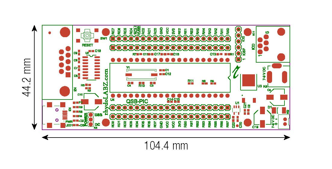 How to test:
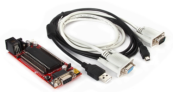
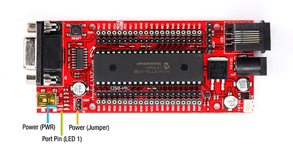
- Mini USB(only for powering) and Serial Cable is used to download program to PIC 16F877A QuickStart board. When USB cable is connected to the PIC 16F877A QuickStart board, “PWR LED”(Red) on the top of QuickStart board module glows, which shows the power indication.
- Step 1: Launch MPLAB IDE, (click here to download)

- Step 2: From MPLAB IDE menu bar, select Project > Project Wizard

- Step 3: The following window opens. Click Next.

- Step 4: Select the device to be programmed from the drop down list and click on “Next”

- Step 5: Select appropriate language tool suite and click on “Next” (here we have used HI-TECH PICC LITE Compiler, click here to download)
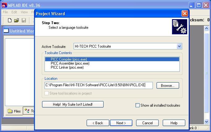
- Step 6: Select the folder to save your project and click on “Next“
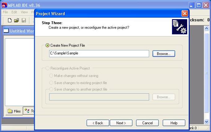
- Step 7: If necessary, you can add existing files to the project and click “Next”
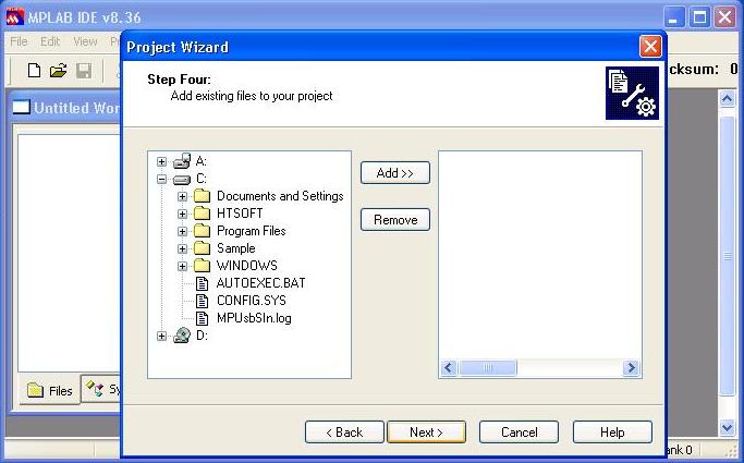
- Step 8: The following window will be shown. Click Finish to finish the project wizard

- Step 9: The following window opens up

- Step 10: Click the New File icon, select File > New or press Ctrl + N. A new window named “Untitled” will open.

- Step 11: Save it in the project folder by File > Save As
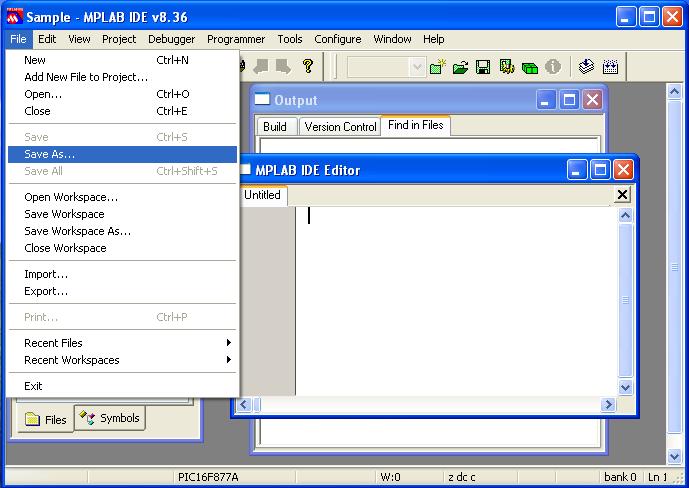
- Step 12: Give suitable name to the file and save it with .c extension

- Step 13: Right click Source Files and select Add Files…

- Step 14: Click Open to add the file to your project

- Step 15: Enter the code for LED blinking(LED1 connected to second pin of PORTB Via jumper “J1”) with 250mS ON time and 250mS OFF time.

- Step 16: Now on building the project, errors and warnings (if any) get listed in the Output window. Correct them and build again. On successful building, the hex file will be generated in the project folder named by the project.

- Step 17: Browse the hex file from the project folder using Tiny Bootloader application.(click here to download)

Step 18: Press and hold reset switch on QS Board and click on the Write Flash button and release reset switch before the load bar empties.
 Note: Before checking the above program, don’t forget to short jumper “J1” (connecting port pin to LED1 on the bottom side of Quick Start Board).
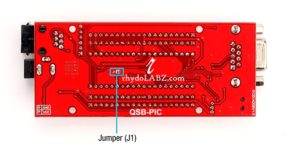
Notable on Board connections
Resources:
How to Buy:

Click here to buy rhydoLABZ PIC16F877A QuickStart board v2.
Click here to buy rhydoLABZ PIC18F4520 QuickStart board v2.
Click here to buy rhydoLABZ PIC18F4580 QuickStart board v2.
Click here to buy rhydoLABZ PIC18F4550 QuickStart board v2.
Support: Please share your ideas with us, visit our forum for discussion
Frequently Asked Questions(FAQ):
Q.Is it possible to use any microcontroller other than PIC 16F877A?
Ans.Yes. The following controllers also can be used
PIC 18F4520
PIC 18F4550
PIC 18F4580
Q.Can I obtain 3.3V from the board?
Ans.Yes. There is an on-board 3.3V regulator whose output is available on berge strip.

Leave a Reply
You must be logged in to post a comment.