ECHO-PRO, 5 in 1 Ultrasonic Module (PWM, ANALOG, ASCII, DET & TEMP)
RhydoLabz “ECHO –PRO, 5in 1” Ultrasonic Distance Sensor is an amazing product that provides very short to long-range detection and ranging with a resolution of 1mm. The ECHO-PRO is a 5 in 1 sensor module which output the distance data as Serial ASCII, Pulse width and Analog output. The module has an on board temperature sensor which outputs the ambient temperature via Serial ASCII. Apart from this the module is also equipped with Proximity sensing output, which will generate a high going signal if any object comes under the preset distance range (1.5-500cm). The ECHO-PRO can operate in “AUTO” mode as well as “Manual” mode. In “Auto” mode the module automatically send the ultrasonic signal and do the measurement and give the distance output, whereas “Manual” mode requires external triggering to initiate distance measurement.

Since there are various interfacing options (ASCII, PWM and ANALOG) available on the module as a standard, it will be easy for a developer to select the optimum one based on the resources available on the microcontroller. No need to buy and stock different modules. In auto mode, the module need mot be triggered saving a control pin. The user can easily interface it with a microcontroller is a free Input, analog or UART Rx pin is available. This module enables a programmer to read temperature value even if an analog pin is not available in that corresponding controller, making it highly versatile.

The sensor provides precise, stable non-contact distance measurements from about 1.8cm to 5 meters with very high accuracy which is way ahead of normal ultrasonic sensors. Its compact size, long range and ease of usability make it a handy sensor for distance measurement and mapping. The board can easily be interfaced to microcontroller RX pin (USART). This sensor is perfect for a number of applications that require you to perform distance measurements while moving or stationary. Naturally, robotics applications are very popular but you’ll also find this product to be useful in security systems or as an infrared replacement if so desired.
Features
- Output : Serial ASCII, Pulse width, Analog, Temperature Output, Proximity Detector
- Range : 1.5 cm to 500cm
- Modes : Auto & Manual Mode Selection
- Resolution : 1-mm (PWM, ASCII)
- Accurate and Stable range data
- Proximity range can be adjusted by Trim pot.
- 10Hz reading rate
- Internal temperature compensation
- 40 kHz Ultrasonic sensor measures distance to objects
- Virtually no sensor dead zone, objects closer than 1.8 cm will typically range as 1.8 cm
- Real-time automatic calibration (voltage, Temperature, ambient noise)
- Automatically Triggered at every 100 ms (Auto Mode)
- On board Proximity Detection LED indication
- On Board Burst LED Indicator shows measurement in progress
- Operating voltage : 3.0V – 5.5V
- Current : <20mA
- Designed for easy integration into your project or product
- Operational Temperature : 0°C to +65°C (+32°F to +149°F)
- Mounting holes provided on the circuit board
- 6-pin header makes it easy to connect using a servo extension cable, no soldering required
- Professional EMI/RFI Complaint PCB Layout Design for Noise Reduction
Applications & Uses
- Bin level measurement
- Proximity zone detection
- People detection
- Robots ranging sensor
- Autonomous navigation Distance measuring
- Long range object detection
Pin Description
ECHO-PRO have 5 pins with bread board compatible DET (Proximity Detection), Gnd (Ground), +5 (Power Supply), PWM (Pulse Width Modulation output), ANG (Analog) and ASCII (Serial data) from right to left.


| Layout |
 Modes of operation.
Echo-Pro is designed to operate in Two modes , Manual mode and Auto mode.
• Manual Mode : Jumper ( J1 ) Shorted
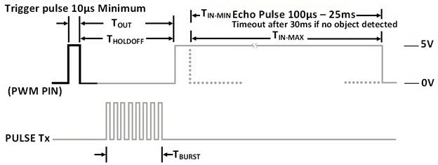
In manual mode, the module needs to be triggered by a External positive going pulse by the user to do the Distance measurement . This trigger pulse should be provided at the PWM pin of the module with High-time ranging from 10µsec – 100µsec, typical value is 10µsec. User need to provide the trigger pulse repeatedly every time before reading DET, PWM, ANG or ASCII pins.
• Auto Mode : Jumper ( J1 ) Open
Auto mode very easy and In this mode, the module automatically triggers and do the distance measurement at every 100ms. In this mode the user can blindly read DET, PWM, ANG or ASCII pins.


Detailed Pin Description
1. DET Pin
DET Pin is an O/P Pin which will be used to show the status the of the Proximity sensing. Proximity detection pin with a default state as LOW , produces a HIGH signal if an obstacle is present within the preset distance of that module. This preset distance could be varied from (1.5 – 500) cm depending upon its application by adjusting the trim pot (P1) on the back of the module . There is an LED indicator that glows as the DET pin goes HIGH. In auto mode the Proximity detection operates without any kind of support from an external micro controller or an external circuit . This will help the developer to use most of the resources of their micro controller for other operations and if any objects comes near or distance to objects reduces ,they will get a interupt request, by connecting DET pin to “INTERRUPT” pin of the controller. To avoid pulse chattering on preseted distance due to external noises ,we have provided a safety window of 1cm. For Example: Suppose the module Generate a HIGH pulse at a preset distance of 10 centimeter by an obtacle , the DET Pin will go LOW only if the the distance to obstacle reaches 11 centimeter.
 2. PWM Pin
PWM pin provides an output pulse with a HIGH time duration depends on the distance to the object. hence the distance to the target can be measured from the width of this pulse. This pulse will be TTL signal with minimum width of 87uS to maximum width of 30mS. As per the sample circuit below, the PWM pin of the ECHO sensor is to be connected to RB2 of the HOST controller. The obtained value (pulse-width) in µSeconds represents the echo time and further calibrations of this data gives you the obstacle distance. Speed of ultrasonic wave is 347 m/s equivalent to 0 .0347cm/µsec (Temperature dependent)
As per the eqn: Speed = distance/time => echo distance (Ed) = echo speed(Ev) *echo time(Et) ie, distance (Ed) = 0.0347cm per µsec (Ev) * Et µsec
The obtained distance will be twice the actual distance since it gives the to and fro distance of the object as per the to and fro time equated to the equation: (ie, Et stands for 2Et).
Thus the obtained distance divided by 2 gives actual distance of the obstacle.
ie, Actual distance = Ed/2.As per the above illustration your equation is,
Ed = Ev * (Et/2) implies Et = 2 * Ed /Ev equivalent to Et = (2/0.0347) *Ed
Implies Et = 58 * Ed equivalent to Ed (in cm) = Et(in µsec)/58
For instance, assume the output waveform produced to be:
 The width of the wave increases with increase in distance between ultrasonic sensor and obstacle.Above graph shows the width of wave i.e 11.617ms.Using this graph we can calculate the distance of object from the sensor.Using above equation the resulting distance of the wave is 200cm.
ie, Ed (in cm) = Et(in µsec)/58
Echo time(Et)=11617 us
Ed=116170/58
Ed=200.29cm
 Above graph shows wave with width of 1.336ms(distance between sensor and obstacle) and the calculated distance is 23 cm.
ie, Ed (in cm) = Et(in µsec)/58 ,
Echo time(Et)=1336 us
Ed =1336/58
Ed=23cm
 Above graph shows wave with width of .271 ms(distance between sensor and obstacle) and the calculated distance is 4.67cm.
ie, Ed (in cm) = Et(in µsec)/58 ,
Echo time(Et)=271 us
Ed=271/58
Ed= 4.67cm
Connection Details for Taking PWM Output

Sample Code For Reading PWM pin in Auto Mode![]()
|
1 2 3 4 5 6 7 8 9 10 11 12 13 14 15 16 17 18 19 20 21 22 23 24 25 26 27 28 29 30 31 32 33 34 35 36 37 38 39 40 41 42 43 44 45 46 47 48 49 50 51 52 53 54 55 56 57 58 59 60 61 62 63 64 65 66 67 68 69 70 71 72 73 74 75 76 77 78 79 80 81 82 83 84 85 86 87 88 89 90 91 92 93 94 95 96 97 98 99 100 101 102 103 104 105 106 107 108 109 110 111 112 113 114 115 116 117 118 119 120 121 122 123 124 125 126 127 128 129 130 131 132 133 134 135 136 137 138 139 140 141 142 143 144 145 146 147 148 149 150 151 152 153 154 155 156 157 158 159 160 161 162 163 164 165 166 167 168 169 170 171 172 173 174 175 176 177 178 179 |
/******************************************************************************************* Microcontroller -- PIC 16F877A - 40-pin-8-bit. Clock Frequency is 20 MHz -- Period in 200 Nano second baudrate-9600. *******************************************************************************************/ #include<pic.h> #include<math.h> #include<string.h> #define START_PULSE_TIMER() T0CS=0 /* echo wait PULSEIN timer stop bit */ #define STOP_PULSE_TIMER() T0CS=1 #define BAUDRATE 9600 /* UART baud rate initialisation */ /* Timer0 interrupt enable */ #define INTERRUPT_ENABLE() GIE=1; T0IF=0; T0IE=1 /* Port configuration */ #define PORT_CONFIG() TRISC=0X00; TRISD=0X00; RBPU=0; TRISB2=1 double PulseInTime=0; /* variable calculating the echo travel time */ double cmDistance; /* variable calculating the distance within limits */ unsigned int tDistance; /* temperary variable for holding the distance value */ unsigned int TimeCnt=0; /* timer0 overflow count */ volatile unsigned char Recdata; /* variable used to store received data */ /******************************************************************************************* Function : Delay_100MicroSec() Description : Delay function for 100 micro-sec *******************************************************************************************/ void Delay_100MicroSec() { int dCnt; /* delay count */ for(dCnt=1;dCnt<35;dCnt++); /* 100Us approx */ } /******************************************************************************************* Function : DelayMs Description : Delay function for n milli-sec, n=1,2,3.... *******************************************************************************************/ void DelayMs(unsigned char Cnt) { int dCnt; /* delay count */ while(Cnt>0) { for(dCnt=0;dCnt<10;dCnt++) /* 10ms delay */ Delay_100MicroSec(); /* 100Us delay */ Cnt--; } } /******************************************************************************************* Function : Uart_Data Description : function used to send single data *******************************************************************************************/ void Uart_Data(char data) { TXREG=data; /* move data to transmission regester */ DelayMs(1); while(TRMT!=1); /* Checking the status of shift regester */ } /******************************************************************************************* Function : Uart_String Description : function used to send string *******************************************************************************************/ void Uart_String(const char *data) { while(*data!='\0') /* checking for null character */ { Uart_Data(*data); /* transmitting data */ data++; /* incrementing array pointer */ } } /******************************************************************************************* Function : Uart_Init Description : function used for basic initialization *******************************************************************************************/ void Uart_Init(unsigned long BAUD_RATE) { if(BAUD_RATE>=9600) { BRGH=1; /* high speed baud rate */ SPBRG=(unsigned long)(20 * (pow(10,6))/((long) (BAUD_RATE * 16))-1); } else { BRGH=0; /* low speed baud rate */ SPBRG=(unsigned long)(20 * (pow(10,6))/((long) (BAUD_RATE * 64))-1); } SYNC=0; /* asynchronous mode - UART */ SPEN=1; /* serial port enable */ TXEN=1; /* transmission enable */ } /******************************************************************************************* Function : Timer0_Init Description : Function used for Timer0 initialization *******************************************************************************************/ void Timer0_Init() { PSA =1; /* set timer0 minimum prescale */ TMR0=0; /* timer0 count register */ T0CS=1; /* timer0 start bit */ } /******************************************************************************************* Function : Conv2DispFormat Description : Function used to concert a decimal number - ascii *******************************************************************************************/ void Conv2DispFormat(unsigned int value) { int i,cnt=1; char DArr[6]; while(value>=10) /* BCD conversion of distance calculated in cm */ { DArr[cnt]=(value%10)+'0'; value=value/10; cnt++; } DArr[cnt]=value+'0'; for(i=cnt;i>=1;i--) Uart_Data(DArr[i]); /* transmit distance in cm */ } /******************************************************************************************* Function : PulseInMode Description : Function used for calculate distance *******************************************************************************************/ void PulseInMode() { while(!RB2); /* wait for PulseIn signal to go HIGH */ START_PULSE_TIMER(); /* start echo PulseIn timer */ while(RB2); /* wait for PulseIn signal to go LOW */ STOP_PULSE_TIMER(); /* stop echo PulseIn timer */ PulseInTime= TMR0; /* timer calculations [return time in Us] */ PulseInTime= (double)( ( (PulseInTime* 0.2) + (TimeCnt * 51.2)) ); /* timer value in Us divided by 58 gives the cm distance */ cmDistance = (double) PulseInTime/58; /* display of the calculated distance */ tDistance =(unsigned int)cmDistance; Uart_String("PWM:"); Conv2DispFormat(tDistance); /* BCD conversion of mantissa and exponential part for UART transmission */ Uart_Data('.'); Conv2DispFormat((unsigned int)((cmDistance - tDistance)*10)); Uart_String("cm "); TimeCnt=0; PulseInTime=0; TMR0=0; Uart_Data(0X0A); Uart_Data(0X0D); } void main() { PORT_CONFIG(); /* PORT configurations */ INTERRUPT_ENABLE(); /* Interrupt enable */ Uart_Init(BAUDRATE); /* Baud definition */ Timer0_Init(); /* Timer initialisation */ while(1) { PulseInMode(); /* PulseIn mode */ DelayMs(250); /* 250 milli-sec delay before next cycle */ DelayMs(250); /* 250 milli-sec delay before next cycle */ } } /******************************************************************************************* Function : interrupt isr Description : interrupt service routine *******************************************************************************************/ void interrupt isr() { T0IF=0; /* clear timer interrupt flag */ TimeCnt++; /* timer overflow count increment */ } |
Sample Code For Reading PWM pin in Manual Mode![]()
|
1 2 3 4 5 6 7 8 9 10 11 12 13 14 15 16 17 18 19 20 21 22 23 24 25 26 27 28 29 30 31 32 33 34 35 36 37 38 39 40 41 42 43 44 45 46 47 48 49 50 51 52 53 54 55 56 57 58 59 60 61 62 63 64 65 66 67 68 69 70 71 72 73 74 75 76 77 78 79 80 81 82 83 84 85 86 87 88 89 90 91 92 93 94 95 96 97 98 99 100 101 102 103 104 105 106 107 108 109 110 111 112 113 114 115 116 117 118 119 120 121 122 123 124 125 126 127 128 129 130 131 132 133 134 135 136 137 138 139 140 141 142 143 144 145 146 147 148 149 150 151 152 153 154 155 156 157 158 159 160 161 162 163 164 165 166 167 168 169 170 171 172 173 174 175 176 177 178 179 180 181 182 183 184 185 186 187 188 189 190 191 192 193 194 195 196 197 198 199 200 |
/******************************************************************************************* Microcontroller -- PIC 16F877A - 40-pin-8-bit. Clock Frequency is 20 MHz -- Period in 200 Nano second baudrate-9600 *******************************************************************************************/ #include<pic.h> #include<math.h> #define START_PULSE_TIMER() T0CS=0 /* echo wait PULSEIN timer stop bit */ #define STOP_PULSE_TIMER() T0CS=1 #define BAUDRATE 9600 /* UART baud rate initialisation */ /* Timer0 interrupt enable */ #define INTERRUPT_ENABLE() GIE=1; T0IF=0; T0IE=1 /* Port configuration */ #define PORT_CONFIG() TRISC=0X00; TRISD=0X00; RBPU=0 double PulseInTime=0; /* variable calculating the echo travel time */ double cmDistance; /* variable calculating the distance within limits */ unsigned int tDistance; /* temperary variable for holding the distance value */ unsigned int TimeCnt=0; /* timer0 overflow count */ volatile unsigned char Recdata; /*variable used to store received data */ /******************************************************************************************* Function : Delay10Us Description : Delay function for 10 micro-sec *******************************************************************************************/ void Delay10Us() { int dCnt; /* delay count */ for(dCnt=0;dCnt<3;dCnt++); /* 10Us approx */ } /******************************************************************************************* Function : Delay_100MicroSec Description : Delay function for 100 micro-sec *******************************************************************************************/ void Delay_100MicroSec() { int dCnt; /* delay count */ for(dCnt=1;dCnt<35;dCnt++); /* 100Us approx */ } /******************************************************************************************* Function : DelayMs Description : Delay function for n milli-sec, n=1,2,3.... *******************************************************************************************/ void DelayMs(unsigned char Cnt) { int dCnt; /* delay count */ while(Cnt>0) { for(dCnt=0;dCnt<10;dCnt++) /* 10ms approx */ Delay_100MicroSec(); /* 100Us approx */ Cnt--; } } /******************************************************************************************* Function : Uart_Data Description : function used to send single data *******************************************************************************************/ void Uart_Data(unsigned char data1) { TXREG=data1; /* load data to tranmission regester */ while(TRMT!=1); /* check for shift regester status */ } /******************************************************************************************* Function : Uart_String Description : function used to send string *******************************************************************************************/ void Uart_String(const char *data) { while(*data !='\0') /* check for null character */ { Uart_Data(*data); /* transmit data via UART */ data++; /* increment array pointer */ } } /******************************************************************************************* Function : Uart_Init Description : function used for basic initialization *******************************************************************************************/ void Uart_Init(unsigned long BAUD_RATE) { if(BAUD_RATE>=9600) { BRGH=1; /* select high speed baud rate */ SPBRG=(unsigned long)(20 * (pow(10,6))/((long) (BAUD_RATE * 16))-1); } else { BRGH=0; /* low speed baud rate */ SPBRG=(unsigned long)(20 * (pow(10,6))/((long) (BAUD_RATE * 64))-1); } SYNC=0; /* asynchronous mode - UART */ SPEN=1; /* serial port enable */ CREN=1; /* continuous reception enable */ TXEN=1; /*Transmision enable */ } /******************************************************************************************* Function : Timer0_Init Description : Function used for Timer0 initialization *******************************************************************************************/ void Timer0_Init() { PSA =1; /* set timer0 minimum prescale */ TMR0=0; /* timer0 count register */ T0CS=1; /* timer0 start bit */ } /******************************************************************************************* Function : Conv2DispFormat Description : convert decimal number into ascii string *******************************************************************************************/ void Conv2DispFormat(unsigned int value) { int i,cnt=1; char darr[6]; while(value>=10) /* BCD conversion of cm distance calculated */ { darr[cnt]=(value%10)+'0'; value=value/10; cnt++; } darr[cnt]=value+'0'; for(i=cnt;i>=1;i--) Uart_Data(darr[i]); /* transmit string */ } /******************************************************************************************* Function : TriggerPulse Description : Function used for Trigger sensor *******************************************************************************************/ void TriggerPulse() { RB2=0; TRISB2=0; /* pulse signal line made O/P for trigger */ Delay10Us(); /* H_to_L transition. ie, Trigger Pulse to the Ultrasonic range finder module */ RB2=1; Delay10Us(); RB2=0; /* clear timer overflow count, pulseIn time and timer register count */ TimeCnt=0; PulseInTime=0; TMR0=0; TRISB2=1; /* pulse signal line made I/P for echo PulseIn */ } /******************************************************************************************* Function : PulseInMode Description : Function used for calculate distance *******************************************************************************************/ void PulseInMode() { while(!RB2); /* wait for PulseIn signal to go HIGH */ START_PULSE_TIMER(); /* start echo PulseIn timer */ while(RB2); /* wait for PulseIn signal to go LOW */ STOP_PULSE_TIMER(); /* stop echo PulseIn timer */ TRISB2=0; /* pulse signal line made O/P */ RB2 =0; /* clear I/O pin */ PulseInTime= TMR0; /* timer calculations [return time in Us] */ /* timer value in Us divided by 58 gives the cm distance */ PulseInTime= (double)( ( (PulseInTime* 0.2) + (TimeCnt * 51.2)) ); cmDistance = (double) PulseInTime/58; /* display of the calculated distance */ tDistance =(unsigned int)cmDistance; Uart_String("PWM:"); Conv2DispFormat(tDistance); /* BCD conversion of mantissa and exponential part for UART transmission */ Uart_Data('.'); Conv2DispFormat((unsigned int)((cmDistance - tDistance)*10)); Uart_String("cm "); Uart_Data(0X0d); Uart_Data(0X0A); } void main() { PORT_CONFIG(); /* PORT configurations */ Uart_Init(BAUDRATE); /* USART-reception initialisation */ INTERRUPT_ENABLE(); /* Interrupt enable */ Timer0_Init(); /* Timer initialisation */ while(1) { TriggerPulse(); /* Trigger mode */ PulseInMode(); /* PulseIn mode */ DelayMs(250); /* 250 milli-sec delay before next cycle */ DelayMs(250); /* 250 milli-sec delay before next cycle */ } } /******************************************************************************************* Function : interrupt isr Description : interrupt service routine *******************************************************************************************/ void interrupt isr() { T0IF=0; /* clear timer interrupt flag */ TimeCnt++; /* timer overflow count increment */ } |
3. ANG Pin
Analog produces an analog output corresponding to the distance to the obstacle, i.e. 9.676mV corresponds to 1cm. This could be measured using an ADC (Analog to Digital Conversion) module. In the sample code provided below, ANG pin is assumed to be connected to ADC channel 6 of a PIC16F877A microcontroller. Default +Vref & –Vref of a PIC microcontroller ADC module is 5V & 0V respectively producing a 10bit digital value for 5v input equallent to 1023(decimal).
1023(decimal) = 5V
1023(decimal) = 5000mV
1(decimal) = (5000/1023) mV
1(decimal) = 4.887 mV
9.676mV corresponds to 1cm & D being the 10 bit ADC output,
Distance in cm = [D*4.88]/9.676cm
For example; if the module produces an output of 2V
The ADC module in the microcontroller converts this 2V analog input to a digital value equivalent to 409.
Now to find the distance in centimeters corresponding to this ADC output.
From the above formulated equation,
Distance in cm = [D*4.88]/9.676cm
Distance in cm = [409*4.88]/9.676cm // Substituting D with 409
Distance in cm = 206cm
Note: In manual mode, the analog voltage will be produced only when a trigger pulse is provided at the PWM pin of the module.
Connection Details for Taking Analog Output
 Sample Code for Reading ANG pin in Auto Mode
![]()
|
1 2 3 4 5 6 7 8 9 10 11 12 13 14 15 16 17 18 19 20 21 22 23 24 25 26 27 28 29 30 31 32 33 34 35 36 37 38 39 40 41 42 43 44 45 46 47 48 49 50 51 52 53 54 55 56 57 58 59 60 61 62 63 64 65 66 67 68 69 70 71 72 73 74 75 76 77 78 79 80 81 82 83 84 85 86 87 88 89 90 91 92 93 94 95 96 97 98 99 100 101 102 103 104 105 106 107 108 109 110 111 112 113 114 115 116 117 118 119 120 121 122 123 124 125 126 127 128 129 130 131 132 133 134 135 136 137 138 139 140 141 142 143 144 145 146 147 148 149 150 151 152 153 154 155 156 |
/******************************************************************************************** Microcontroller -- PIC 16F877A - 40-pin-8-bit. Clock Frequency is 20 MHz -- Period in 200 Nano second baudrate-9600. ********************************************************************************************/ #include<pic.h> #include<math.h> #include<string.h> #define BAUDRATE 9600 /* Baud rate for UART initialisation */ /* Configuring the PORTs */ #define PORT_CONFIG() TRISC=0X00; TRISD=0X00;TRISE=0X0F volatile unsigned char Recdata; /* Variable used to store received data */ int Adc_Value=0; /* Temporary variable */ int ab; /* Variable to store ADC result */ /******************************************************************************************** Function : Delay_100MicroSec Description : Delay function for 100 micro-second ********************************************************************************************/ void Delay_100MicroSec() { int dCnt; /* Delay count */ for(dCnt=1;dCnt<35;dCnt++); /* 100 us approx */ } /******************************************************************************************** Function : DelayMs Description : Delay function for n milli-second, n=1,2,3.... ********************************************************************************************/ void DelayMs(unsigned char Cnt) { int dCnt; /* Delay count */ while(Cnt>0) /* count check */ { for(dCnt=0;dCnt<10;dCnt++) /* 1ms approx */ Delay_100MicroSec(); /* 100 us approx */ Cnt--; } } /******************************************************************************************** Function : Uart_Data Description : Function used to send single character ********************************************************************************************/ void Uart_Data(char data1) { TXREG=data1; /* The data to be sent is loaded to TXREG */ while(TRMT!=1); /* Wait here till the data is transmitted */ } /******************************************************************************************** Function : Uart_String Description : Function used to send string ********************************************************************************************/ void Uart_String(const char *data1) { while(*data1!='\0') /* Checking the end of string */ { Uart_Data(*data1); data1++; } } /******************************************************************************************** Function : Uart_Init Description : Function used for UART initialisation ********************************************************************************************/ void Uart_Init(unsigned long BAUD_RATE) { if(BAUD_RATE>=9600) { BRGH=1; /* Select high speed baud rate */ SPBRG=(unsigned long)(20 * (pow(10,6))/((long) (BAUD_RATE * 16))-1); } else { BRGH=0; /* Low speed baud rate */ SPBRG=(unsigned long)(20 * (pow(10,6))/((long) (BAUD_RATE * 64))-1); } SYNC=0; /* Asynchronous mode - UART */ SPEN=1; /* Serial port enable */ TXEN=1; /* Transmission enable */ } /******************************************************************************************** Function : Conv2DispFormat Description : Function used to display value ********************************************************************************************/ void Conv2DispFormat(unsigned int value) { int i,cnt=1; char DArr[6]; while(value>=10) /* BCD conversion of distance(in cm) calculated */ { DArr[cnt]=(value%10)+'0'; value=value/10; cnt++; } DArr[cnt]=value+'0'; for(i=cnt;i>=1;i--) { Uart_Data(DArr[i]); /* Transmitting the converted data */ } } /******************************************************************************************** Function : Adc_init Description : Function used to Initialise ADC module ********************************************************************************************/ void ADC_init() { ADFM=1; /* ADC result is right justified */ PCFG3=0; /* Configure pins in analog mode */ PCFG2=0; PCFG1=0; PCFG0=0; } /******************************************************************************************** Function : Adc_Conversion Description : Function used for ADC conversion ********************************************************************************************/ int Adc_Conversion(int channel) { ADCON0=0x81|channel<<3; /* Selecting the ADC channel in ADCON0 */ DelayMs(5); ADGO=1; /* Start ADC conversion */ while(ADGO!=0); /* Wait here till conversion is over */ ab=ADRESH; /* Assigning the ADC result to ab */ ab=ADRESH<<8; ab=ab|ADRESL; return(ab); /* Return ADC result */ } void main() { PORT_CONFIG(); /* PORT configuration */ ADC_init(); /* ADC initialisation */ Uart_Init(BAUDRATE); /* USART initialisation */ while(1) { Adc_Value=Adc_Conversion(6); /* The sensor is connected to channel 6 */ Adc_Value=(int)((Adc_Value*4.883)/9.676); /* ADC value calibration (1cm=9.676mV) */ Uart_String("ADC:"); Conv2DispFormat(Adc_Value); Uart_String("cm "); Uart_Data(0X0A); Uart_Data(0X0D); } } |
Sample Code for Reading ANG pin in Manual Mode![]()
|
1 2 3 4 5 6 7 8 9 10 11 12 13 14 15 16 17 18 19 20 21 22 23 24 25 26 27 28 29 30 31 32 33 34 35 36 37 38 39 40 41 42 43 44 45 46 47 48 49 50 51 52 53 54 55 56 57 58 59 60 61 62 63 64 65 66 67 68 69 70 71 72 73 74 75 76 77 78 79 80 81 82 83 84 85 86 87 88 89 90 91 92 93 94 95 96 97 98 99 100 101 102 103 104 105 106 107 108 109 110 111 112 113 114 115 116 117 118 119 120 121 122 123 124 125 126 127 128 129 130 131 132 133 134 135 136 137 138 139 140 141 142 143 144 145 146 147 148 149 150 151 152 153 154 155 156 157 158 159 160 161 162 163 164 165 166 167 168 169 170 171 172 173 174 175 176 177 178 179 180 181 182 |
/******************************************************************************************** Microcontroller -- PIC 16F877A - 40-pin-8-bit. Clock Frequency is 20 MHz -- Period in 200 Nano second baudrate-9600. ********************************************************************************************/ #include<pic.h> #include<math.h> #define BAUDRATE 9600 /* UART Baud rate initialisation */ /* Configuring the PORTs */ #define PORT_CONFIG() TRISC=0X00; TRISD=0X00; TRISE=0X0F; RBPU=0 volatile unsigned char Recdata; /* Variable used to store received data */ int Adc_Value=0; /* Temporary variable */ int ab; /* Variable to store ADC result */ /******************************************************************************************** Function : Delay10Us Description : Delay function for 10 micro-second ********************************************************************************************/ void Delay10Us() { int dCnt; /* Delay count */ for(dCnt=0;dCnt<3;dCnt++); /* 10 us approx */ } /******************************************************************************************** Function : Delay_100MicroSec Description : Delay function for 100 micro-second ********************************************************************************************/ void Delay_100MicroSec() { int dCnt; /* Delay count */ for(dCnt=1;dCnt<35;dCnt++); /* 100 us approx */ } /******************************************************************************************** Function : DelayMs Description : Delay function for n milli-second, n=1,2,3.... ********************************************************************************************/ void DelayMs(unsigned char Cnt) { int dCnt; /* Delay count */ while(Cnt>0) /* count check */ { for(dCnt=0;dCnt<10;dCnt++) /* 1ms approx */ Delay_100MicroSec(); /* 100 us approx */ Cnt--; } } /******************************************************************************************** Function : Uart_Data Description : Function used to send single character ********************************************************************************************/ void Uart_Data(char data1) { TXREG=data1; /* The data to be sent is loaded to TXREG */ while(TRMT!=1); /* Wait here till the data is transmitted */ } /******************************************************************************************** Function : Uart_String Description : Function used to send string ********************************************************************************************/ void Uart_String(const char *data1) { while(*data1!='\0') /* Checking the end of string */ { Uart_Data(*data1); /* Transmit array character */ data1++; /* Increment array pointer */ } } /******************************************************************************************** Function : Uart_Init Description : Function used for UART initialisation ********************************************************************************************/ void Uart_Init(unsigned long BAUD_RATE) { if(BAUD_RATE>=9600) { BRGH=1; /* Select high speed baud rate */ SPBRG=(unsigned long)(20 * (pow(10,6))/((long) (BAUD_RATE * 16))-1); } else { BRGH=0; /* Low speed baud rate */ SPBRG=(unsigned long)(20 * (pow(10,6))/((long) (BAUD_RATE * 64))-1); } SYNC=0; /* Asynchronous mode - UART */ SPEN=1; /* Serial port enable */ TXEN=1; /* UART transmission enable */ } /******************************************************************************************** Function : Conv2DispFormat Description : Function used to display value ********************************************************************************************/ void Conv2DispFormat(unsigned int value) { int i,cnt=1; char DArr[6]; while(value>=10) /* BCD conversion of distance(in cm) calculated */ { DArr[cnt]=(value%10)+'0'; value=value/10; cnt++; } DArr[cnt]=value+'0'; for(i=cnt;i>=1;i--) { Uart_Data(DArr[i]); /* Transmitting the converted data */ } } /******************************************************************************************** Function : Adc_init Description : Function used to initialise ADC module ********************************************************************************************/ void ADC_init() { ADFM=1; /* ADC result is right justified */ PCFG3=0; /* Configure pins in analog mode */ PCFG2=0; PCFG1=0; PCFG0=0; } /******************************************************************************************** Function : Adc_Conversion Description : Function used for ADC conversion ********************************************************************************************/ int Adc_Conversion(int channel) { ADCON0=0x81|channel<<3; /* Selecting the ADC channel in ADCON0 */ DelayMs(5); ADGO=1; /* Start ADC conversion */ while(ADGO!=0); /* Wait here till conversion is over */ ab=ADRESH; /* Assigning the ADC result to ab */ ab=ADRESH<<8; ab=ab|ADRESL; return(ab); /* Return ADC result */ } /******************************************************************************************** Function : TriggerPulse Description : Function used to trigger sensor ********************************************************************************************/ void TriggerPulse() { TRISB2=0; /* Pulse signal line made O/P for trigger */ RB2=0; Delay10Us(); RB2=1; /* H_to_L Trigger Pulse of 10 us to the Ultrasonic range finder module */ Delay10Us(); RB2=0; TRISB2=1; /* Pulse signal line made I/P */ } void main() { PORT_CONFIG(); /* PORT configurations */ ADC_init(); /* ADC initialisation */ Uart_Init(BAUDRATE); /* USART initialisation */ while(1) { TriggerPulse(); Adc_Value=Adc_Conversion(6); /* The sensor is connected to channel 6 */ Adc_Value=(int)((Adc_Value*4.883)/9.676); /* ADC value calibration (1cm=9.676mV) */ Uart_String("ADC:"); Conv2DispFormat(Adc_Value); Uart_String("cm "); Uart_Data(0X0d); Uart_Data(0X0A); } } |
4. ASCII Pin
ASCII Serial Data output produces a TTL (Transistor Transistor Logic) output at a baud rate of 9600 including both distance and temperature sensor outputs in the format “DXXX.XTXXX” along with a ‘\r’ symbolizing the end of the string. For example “D145.6T030” where ‘D’ followed by distance in centimeters and ‘T’ followed temperature in degree Celsius. Here the user doesn’t need to calibrate the value read making it easier to interface. Now what if an error occurs while calculating distance? At this point, the module displays an error message instead of displays false readings which greatly increases the reliability of the module. Error output will be in the format “ERRX.XTXXX” also followed by a ‘\r’ to denote the end of the string. For example “ERR0.1T039”, here by checking for an “ERR” in the received string, the user can distinguish valid data from error value.
Note: Serial data outputs calibrated distance & temperature readings, this temperature reading could only be obtained from ASCII pin.
Connection Details for Taking ASCII Output
 Sample Code for Reading ASCII pin in Auto Mode
![]()
|
1 2 3 4 5 6 7 8 9 10 11 12 13 14 15 16 17 18 19 20 21 22 23 24 25 26 27 28 29 30 31 32 33 34 35 36 37 38 39 40 41 42 43 44 45 46 47 48 49 50 51 52 53 54 55 56 57 58 59 60 61 62 63 64 65 66 67 68 69 70 71 72 73 74 75 76 77 78 79 80 81 82 83 84 85 86 87 88 89 90 91 92 93 94 95 96 97 98 99 100 101 102 103 104 105 106 107 108 109 110 111 112 113 114 115 116 117 118 119 120 121 122 123 124 125 126 127 128 129 130 131 132 133 134 135 136 137 138 139 140 141 142 143 144 145 146 147 148 149 150 151 152 153 154 155 156 157 158 159 160 161 162 163 164 165 166 167 168 169 170 171 172 173 174 175 176 177 178 179 180 181 182 183 184 185 186 187 188 189 190 191 192 193 194 195 196 197 198 199 200 201 202 203 204 205 206 207 208 209 210 211 212 213 214 215 216 217 218 219 220 221 222 223 224 225 226 227 228 229 230 231 232 |
/******************************************************************************************** Microcontroller -- PIC 16F877A - 40-pin-8-bit. Clock Frequency is 20 MHz -- Period in 200 Nano second baudrate-9600. ********************************************************************************************/ #include<pic.h> #include<math.h> #define BAUDRATE 9600 /* UART baud rate initialisation */ /* Reception interrupt enable */ #define INTERRUPT_ENABLE() GIE=1; PEIE=1; RCIE=1 /* Port configuration */ #define PORT_CONFIG() TRISC=0X80; TRISD=0X00; volatile unsigned char Recdata; /* Variable used to store received data */ unsigned char k=0; /* Temporary variable */ char Temp_Arr[5]; /* Array holding received Temperature value*/ char Dist_Arr[6]; /* Array holding received Temperature value*/ char Err_Arr[5]; /* Array holding received Temperature value*/ /* Generate custom character for degree celcius */ char Custom_Character[8]={0x8,0x14,0x08,0x3,0x4,0x4,0x03,0x0}; bit Dist_flag=0; /* Distance measure flag */ bit Temp_flag=0; /* Temperature measure flag */ bit Err_flag=0; /* Error flag */ bit Err_check=0; /* Error check flag */ bit Start=0; /* Ready for display flag */ /******************************************************************************************** Function : Delay10Us Description : Delay function for 10 micro-sec ********************************************************************************************/ void Delay10Us() { int dCnt; /* Delay count */ for(dCnt=0;dCnt<3;dCnt++); /* 10Us approx */ } /******************************************************************************************** Function : Delay_100MicroSec Description : Delay function for 100 micro-sec ********************************************************************************************/ void Delay_100MicroSec() { int dCnt; /* Delay count */ for(dCnt=1;dCnt<35;dCnt++); /* 100Us approx */ } /******************************************************************************************** Function : DelayMs Description : Delay function for n milli-second, n=1,2,3.... ********************************************************************************************/ void DelayMs(unsigned char Cnt) { int dCnt; /* Delay count */ while(Cnt>0) /* count check */ { for(dCnt=0;dCnt<10;dCnt++) /* 1ms approx */ Delay_100MicroSec(); /* 100Us approx */ Cnt--; } } /******************************************************************************************** Function : Uart_Data Description : function used to send single data ********************************************************************************************/ void Uart_Data(char data) { TXREG=data; /* move data to transmission regester */ DelayMs(1); while(TRMT!=1); /* Checking the status of shift regester */ } /******************************************************************************************** Function : Uart_String Description : function used to send string ********************************************************************************************/ void Uart_String(const char *data) { while(*data!='\0') /* checking for null character */ { Uart_Data(*data); /* transmitting data */ data++; /* incrementing array pointer */ } } /******************************************************************************************** Function : Uart_Init Description : Function used for UART initialization ********************************************************************************************/ void Uart_Init(unsigned long BAUD_RATE) { if(BAUD_RATE>=9600) { BRGH=1; /* Select high speed baud rate */ SPBRG=(unsigned long)(20 * (pow(10,6))/((long) (BAUD_RATE * 16))-1); } else { BRGH=0; /* Low speed baud rate */ SPBRG=(unsigned long)(20 * (pow(10,6))/((long) (BAUD_RATE * 64))-1); } SYNC=0; /* Asynchronous mode - UART */ SPEN=1; /* Serial port enable */ CREN=1; /* Continuous reception enable */ TXEN=1; } /******************************************************************************************** Function : TriggerPulse Description : Function used to trigger sensor ********************************************************************************************/ void TriggerPulse() { RB2=0; TRISB2=0; /* Pulse signal line made O/P for trigger */ Delay10Us(); /* H_to_L transition. ie, Trigger Pulse to the Ultrasonic range finder module */ RB2=1; Delay10Us(); RB2=0; /* Clear timer overflow count, pulseIn time and timer register count */ } void main() { PORT_CONFIG(); /* PORT configurations */ DelayMs(1); Uart_Init(BAUDRATE); /* USART-reception initialisation */ INTERRUPT_ENABLE(); /* Interrupt enable */ RCIF=0; while(1) { if((Start==1)) /* Wait for Start flag */ { if(Err_check==0) /* Error check */ { Uart_String("Dist:"); Uart_String(Dist_Arr); /* Display distance string */ Uart_String("cm"); } else { Uart_String(Err_Arr); /* Display error string */ Err_check=0; } Uart_String("Temp:"); Uart_String(Temp_Arr); /* Display temp. string */ Uart_Data(0X0d); Uart_Data(0X0A); while(Recdata!='\r'); /* wait for end of rec. string */ Start=0; /* enable rec. data comparison */ } } } /******************************************************************************************** Function : interrupt isr Description : Interrupt Service Routine ********************************************************************************************/ void interrupt isr() { if(RCIF==1) { RCIF=0; /* Clear reception interrupt flag */ Recdata=RCREG; if(Start==0) { switch(Recdata) { case 'D': Dist_flag=1; /* To start storing Distance value */ Temp_flag=0;Err_flag=0; k=0; break; case 'T': Temp_flag=1; /* To start storing Temprature value */ Dist_flag=0;Err_flag=0; k=0; break; case 'E': Err_flag=1; /* To display error value */ Dist_flag=0; Temp_flag=0; k=0; break; case '\r':Start=1; /* To check end character of Rec. string */ Err_check=0; if(Err_flag==1) Err_check=1; Temp_flag=0; Err_flag=0; Dist_flag=0; k=0; break; default: if((Dist_flag==1)) /* To store Distance value in array */ { Dist_Arr[k]=Recdata; /* store Distance value in array location */ k++; /* increment array location */ Dist_Arr[k]='\0'; /* insert null character */ } else if((Temp_flag==1) ) /* To store Temp. value in array */ { Temp_Arr[k]=Recdata; /* store Temp. value in array location */ k++; /* increment array location */ Temp_Arr[k]='\0'; /* insert null character */ } else if((Err_flag==1) ) /* To store Error value in array */ { if(k==0) { Err_Arr[k]='E'; k++; } Err_Arr[k]=Recdata; /* store error indication in an array */ k++; /* increment array location */ Err_Arr[k]='\0'; /* insert null character */ } break; } } } } |
Sample Code for Reading ASCII pin in Manual Mode![]()
|
1 2 3 4 5 6 7 8 9 10 11 12 13 14 15 16 17 18 19 20 21 22 23 24 25 26 27 28 29 30 31 32 33 34 35 36 37 38 39 40 41 42 43 44 45 46 47 48 49 50 51 52 53 54 55 56 57 58 59 60 61 62 63 64 65 66 67 68 69 70 71 72 73 74 75 76 77 78 79 80 81 82 83 84 85 86 87 88 89 90 91 92 93 94 95 96 97 98 99 100 101 102 103 104 105 106 107 108 109 110 111 112 113 114 115 116 117 118 119 120 121 122 123 124 125 126 127 128 129 130 131 132 133 134 135 136 137 138 139 140 141 142 143 144 145 146 147 148 149 150 151 152 153 154 155 156 157 158 159 160 161 162 163 164 165 166 167 168 169 170 171 172 173 174 175 176 177 178 179 180 181 182 183 184 185 186 187 188 189 190 191 192 193 194 195 196 197 198 199 200 201 202 203 204 205 206 207 208 209 210 211 212 213 214 215 216 217 218 219 220 221 222 223 224 225 226 227 228 229 230 231 232 233 234 |
/******************************************************************************************** Microcontroller -- PIC 16F877A - 40-pin-8-bit. Clock Frequency is 20 MHz -- Period in 200 Nano second baudrate-9600. ********************************************************************************************/ #include<pic.h> #include<math.h> #define BAUDRATE 9600 /* UART baud rate initialisation */ /* Reception interrupt enable */ #define INTERRUPT_ENABLE() GIE=1; PEIE=1; RCIE=1 /* Port configuration */ #define PORT_CONFIG() TRISC=0X80; TRISD=0X00; RBPU=0 volatile unsigned char Recdata; /* variable used to store received data */ unsigned char k=0; /* temperary variables */ bank1 char Temp_Arr[5]; /* array holding received Temprature value */ bank1 char Dist_Arr[6]; /* array holding received Temprature value */ bank1 char Err_Arr[5]; /* array holding received Temprature value */ char Custom_Character[8]={0x8,0x14,0x08,0x3,0x4,0x4,0x03,0x0}; /* Generate custom character for degree celcious */ bit Dist_flag=0; /* Distance measure flag */ bit Temp_flag=0; /* Temprature measure flag */ bit Err_flag=0; /* Error flag */ bit Err_check=0; /* Error check flag */ bit start=0; /* ready for display flag */ /******************************************************************************************** Function : Delay10Us Description : Delay function for 10 micro-sec ********************************************************************************************/ void Delay10Us() { int dCnt; /* Delay count */ for(dCnt=0;dCnt<3;dCnt++); /* 10Us approx */ } /******************************************************************************************** Function : Delay_100MicroSec Description : Delay function for 100 micro-sec ********************************************************************************************/ void Delay_100MicroSec() { int dCnt; /* Delay count */ for(dCnt=1;dCnt<35;dCnt++); /* 100Us approx */ } /******************************************************************************************** Function : DelayMs Description : Delay function for n milli-second, n=1,2,3.... ********************************************************************************************/ void DelayMs(unsigned char Cnt) { int dCnt; /* Delay count */ while(Cnt>0) /* count check */ { for(dCnt=0;dCnt<10;dCnt++) /* 1ms approx */ Delay_100MicroSec(); /* 100Us approx */ Cnt--; } } /******************************************************************************************** Function : Uart_Data Description : function used to send single data ********************************************************************************************/ void Uart_Data(char data) { TXREG=data; /* move data to transmission regester */ DelayMs(1); while(TRMT!=1); /* Checking the status of shift regester */ } /******************************************************************************************** Function : Uart_String Description : function used to send string ********************************************************************************************/ void Uart_String(const char *data) { while(*data!='\0') /* checking for null character */ { Uart_Data(*data); /* transmitting data */ data++; /* incrementing array pointer */ } } /******************************************************************************************** Function : Uart_Init Description : function used for basic initialization ********************************************************************************************/ void Uart_Init(unsigned long BAUD_RATE) { if(BAUD_RATE>=9600) { BRGH=1; /* select high speed baud rate */ SPBRG=(unsigned long)(20 * (pow(10,6))/((long) (BAUD_RATE * 16))-1); } else { BRGH=0; /* low speed baud rate */ SPBRG=(unsigned long)(20 * (pow(10,6))/((long) (BAUD_RATE * 64))-1); } SYNC=0; /* asynchronous mode - UART */ SPEN=1; /* serial port enable */ CREN=1; /* continuous reception enable */ TXEN=1; /* Transmision enable */ } /******************************************************************************************** Function : TriggerPulse Description : Function used for Trigger sensor ********************************************************************************************/ void TriggerPulse() { TRISB2=0; /* pulse signal line made O/P for trigger */ RB2=0; Delay10Us(); /* H_to_L transition. ie, Trigger Pulse to the Ultrasonic range finder module */ RB2=1; Delay10Us(); RB2=0; /* clear timer overflow count, pulseIn time and timer register count */ Delay10Us(); TRISB2=1; /* pulse signal line made I/P */ } void main() { PORT_CONFIG(); /* PORT configurations */ DelayMs(1); Uart_Init(BAUDRATE); /* USART-reception initialisation */ INTERRUPT_ENABLE(); /* Interrupt enable */ RCIF=0; while(1) { TriggerPulse(); /* Generate trigger pulse */ if((start==1)) /* wait for start flag */ { if(Err_check==0) /* Error check */ { Uart_String("Dist:"); Uart_String(Dist_Arr); /* Display distance string */ Uart_String("cm"); } else { Uart_String(Err_Arr); /* Display error string */ Err_check=0; } Uart_String("Temp:"); Uart_String(Temp_Arr); /* Display temp. string */ Uart_Data(0X0D); Uart_Data(0X0A); start=0; /* enable rec. data comparison */ Dist_flag=0;Temp_flag=0;Err_flag=0; } } } /******************************************************************************************** Function : interrupt isr Description : Interrupt Service Routine ********************************************************************************************/ void interrupt isr() { if(RCIF==1) { RCIF=0; /* Clear reception interrupt flag */ Recdata=RCREG; if(start==0) { switch(Recdata) { case 'D': Dist_flag=1; /* To start storing Distance value */ Temp_flag=0;Err_flag=0; k=0; break; case 'T': Temp_flag=1; /* To start storing Temprature value */ Dist_flag=0;Err_flag=0; k=0; break; case 'E': Err_flag=1; /* To display error value */ Dist_flag=0; Temp_flag=0; k=0; break; case '\r':start=1; /* To check end character of Rec. string */ Err_check=0; if(Err_flag==1) Err_check=1; Temp_flag=0; Err_flag=0; Dist_flag=0; k=0; break; default: if((Dist_flag==1)) /* To store Distance value in array */ { Dist_Arr[k]=Recdata; /* store Distance value in array location */ k++; /* increment array location */ Dist_Arr[k]='\0'; /* insert null character */ } else if((Temp_flag==1) ) /* To store Temp. value in array */ { Temp_Arr[k]=Recdata; /* store Temp. value in array location */ k++; /* increment array location */ Temp_Arr[k]='\0'; /* insert null character */ } else if((Err_flag==1) ) /* To store Error value in array */ { if(k==0) { Err_Arr[k]='E'; k++; } Err_Arr[k]=Recdata; /* store error indication in an array */ k++; /* increment array location */ Err_Arr[k]='\0'; /* insert null character */ } break; } } } } |
How to Buy
Click here to buy rhydoLABZ ECHO-PRO ( 5 in 1 Distance Sensor Module)
Support
Please share your ideas with us, visit our forum for discussion.
Frequently Asked Questions(FAQ)
Q: Is it possible to take readings from DET, ASCII, ANG & PWM pins of the module?
Ans: Yes, you can. It provides output in all the four pins of the module once triggered. The point to be noted is the mode in which the module works. In auto mode, the module automatically triggers to produce an output in a constant rate. But in manual mode, the module outputs data only when a trigger pulse is produced externally.
Q: What will be the DET & ANG outputs in manual mode in the absence of trigger pulse?
Ans: In the absence of trigger the pulse, there won’t be any output in ASCII and PWM pins. But DET & ANG pins retains the previously produced output and changes only when it is triggered.
Q: I have designed a circuit for parallax ping ultrasonic sensor, will this module be compatible with the mentioned circuit?
Ans: Yes, it is compatible. GND, 5V & PWM pins of ECHO-PRO ultrasonic sensor is designed to match the pin-out of parallax ping ultrasonic sensor. Both sensor spacing and board dimensions matches the layout of parallax ping ultrasonic sensor.
Leave a Reply
You must be logged in to post a comment.