Familiarization of BLueLink-HC (RS232)
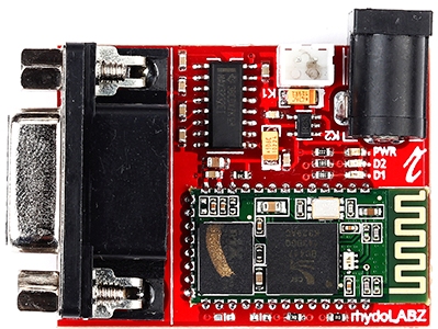
BLueLink-HC RS232 is a low cost, easy to use Bluetooth module that provides wireless communication using RS-232 protocol. You can directly interface it to PC or MCU using serial cable without any additional level converter circuitry.
 It has two modes of operation namely AT command (Order response) mode and Data communication mode.
- In AT command mode, the user can configure different control parameters which finally determine the working of the module. In this mode it can’t communicate with other devices.
- In Data communication mode, the device works as per the settings previously defined by the user in AT command mode and communicates with other devices.
Features
- On board 3.3V regulator
- DC barrel jack and RMC connector for input power supply
- RS 232 interface with on-board MAX 232 and programmable baud rate
- Comes with integrated antenna
- Indication LEDs – Status LED (D2-Red), Power LED (PWR-Blue) and Pair LED (D1-Green)
Module Specifications
- Speed: Asynchronous: 2.1Mbps(Max) / 160 kbps, Synchronous: 1Mbps/1Mbps
- Security: Authentication and encryption
- Profiles: Bluetooth serial port
- Typical -80dBm sensitivity
- Up to +4dBm RF transmit power
- Default Baud rate: 38400
- Data bits:8, Stop bit:1, Parity: No parity
- Supported baud rates: 9600, 19200, 38400, 57600, 115200, 230400 and 460800.
- Auto-connect to the last paired device when powered
- Auto-pairing PIN CODE:”0000” as default
- Pairing PIN CODE:”1234” as default
LED Indications
- Power LED: When the module is powered, Blue LED will glow.
- Status LED: Indicates status of the module.
i. AT Mode (LED blinks once a second): When the module is powered and PIN34 (Key) is given high level, Status LED flickers slowly once a second. It indicates that the module is in AT mode, and the baud rate is 38400.
ii. Unpaired Mode (LED blinks two times a second): When the module is powered and PIN34 (Key) is given low level or floating, Status LED flickers quickly indicating that the module is in pairable mode.
iii. Paired Mode (LED double flicker per second): Pairing is finished and module can communicate.
- Pair LED: Glows when connection is established with another Bluetooth module.
Mode Selection
 PIO11 (Key) is for mode selection. By default the module is in AT Command mode and the default baud rate is 38400. In this mode we can change the Bluetooth name, baud rate, pass key, and Master, slave or auto connect etc.
How to get to AT mode?
Step 1: Open the Key pin to give 3.3V to PIO11.
Step 2: Supply power to the module.
How to get to communication mode?
Step 1: Short the Key pin to give ground to PIO11.
Step 2: Supply power to the module.
Pin Layout
Pin Description
 Changing the module configurations in AT command mode
In AT command mode, open the Key pin to give 3.3V to PIO11 and give supply power to the module.In this we can configure the different control parameters which finally determine the working of the module. In this mode we can’t communicate with other devices.
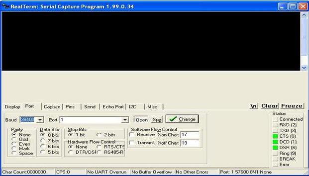
Connect the module to PC and open terminal with COM1. Set baud rate as 38400 (The default baud rate for AT command mode is 38400)
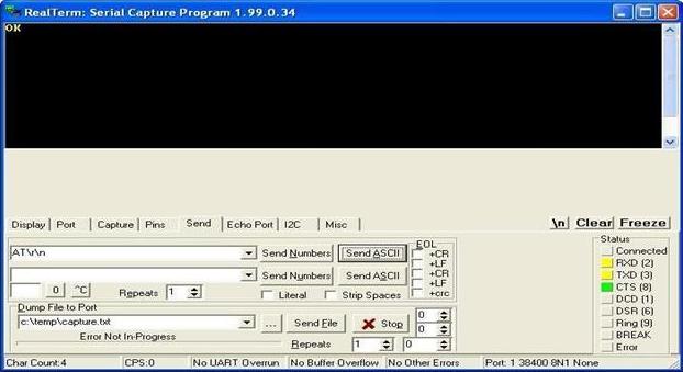
Send the command AT followed by \r\n. The module returns “OK” as response. If any other response is received, send AT command till you get “OK”.
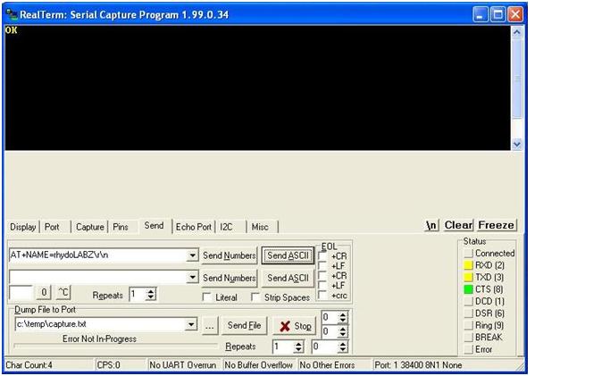
Device name can be set using the command “AT+NAME=<parameter>”
Send command AT+NAME=rhydoLABZ followed by \r\n
Again the module returns “OK” as response
Similarly by using different other AT commands, you can set the module configurations.
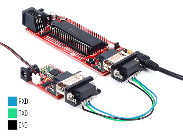
You can use BLueLink-HC RS232 to communicate with other Bluetooth enabled devices.![]()
In Data communication mode,short the Key pin to give ground to PIO11 and give supply power to the module. Here the device works as per the settings previously defined by the user in AT command mode and can communicates with other devices.
- BLueLink-HC RS232 used in PC to PC communication
- BLueLink-HC RS232 used in PC to smartphone communication
- BLueLink-HC RS232 used in PC to MCU communication
- BLueLink-HC RS232 used in MCU to MCU communication
BLueLink-HC RS232 used in PC to PC communication
Connect BLueLink-HC RS232 to a PC and power it. From ‘Device manager’, get the COM port to which the module is connected and open Terminal with the same COM.
In another PC, plug-in Tiny Bluetooth Dongle and open Bluetooth interfacing software. We have used BlueSoleil 2.7.0.41. It automatically detects the Bluetooth devices connected to PC. You will see the following window.
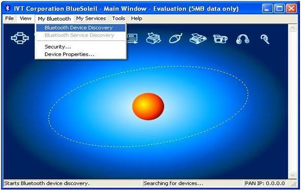
To search Bluetooth devices, press the red button in the middle. The software displays status as ‘Searching for devices…’ You can also do this by “My Bluetooth > Bluetooth Device Discovery”. After the search is complete, you can see that the Bluetooth module with device name rhydoLABZ gets detected.

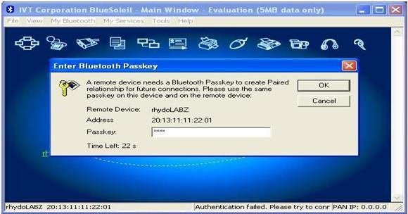
To establish connection, right click the rhydoLABZ icon and click connect. If the module is not already paired, it may ask a passcode. Give the passcode (1234 by default) and click OK.
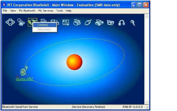
Now Bluetooth connection is established between BLueLink-HC RS232 and Tiny Bluetooth Dongle.The window will be as shown below.

To get the COM port to which Bluesoleil got connected use “Connect” option as shown in the image below. Open Terminal with same COM
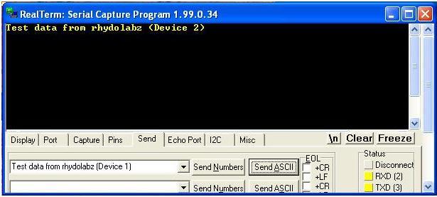
Now check the data transfer between the PCs through Terminals.
BLueLink-HC RS232 used in PC to smartphone communication
- Connect BLueLink-HC RS232 to PC. By default, the module is slave
- Get the COM to which the module is connected.
- Open Terminal with the same COM and desired baud rate.
- Enable Bluetooth in your smartphone and search the module.
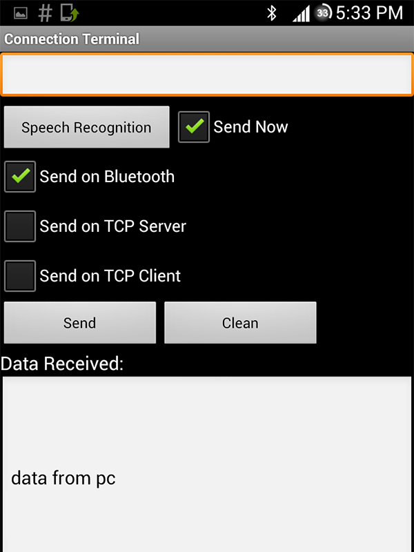
- You can use the Android application “Connection Terminal” in your smart phone to check the data transfer.
- Green LED glows when connection is established.
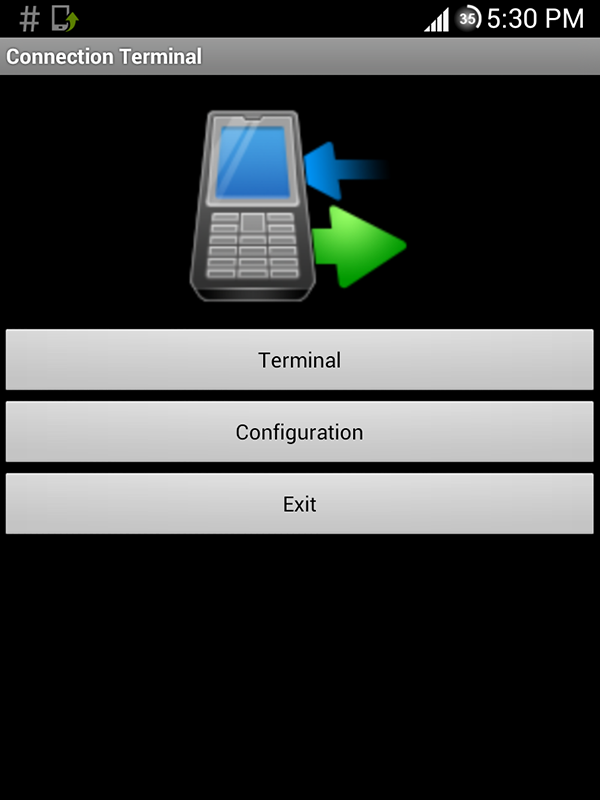
How to use Connection Terminal
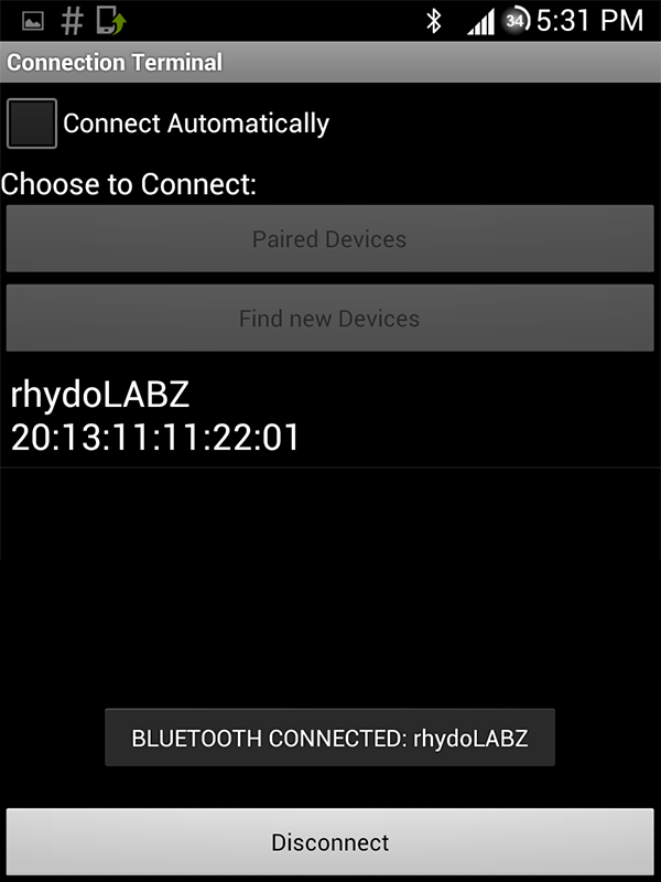
In the home screen of “Connection Terminal”, click Configuration.
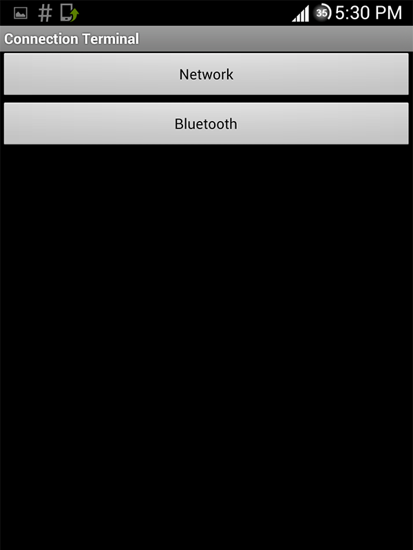
Select Bluetooth option
You can search new devices or connect to already paired devices
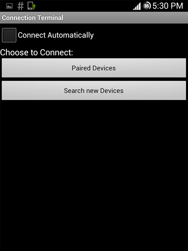
Select the device
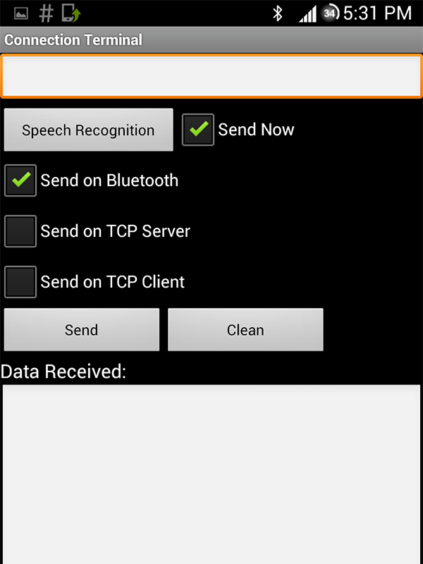
To send data, select send option and type the data
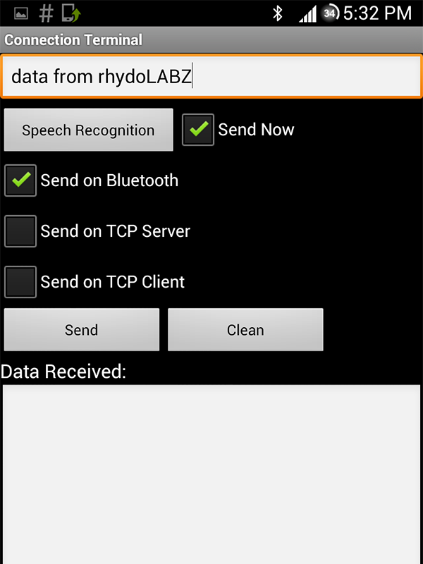
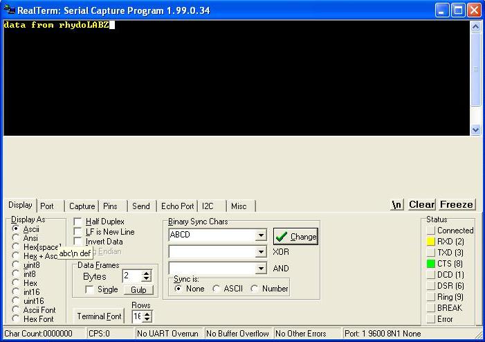
The data received on PC can be read from Terminal
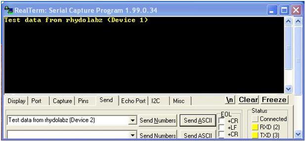
Send data from PC
You can see the received data in Terminal as shown below.
BLueLink-HC RS232 used in PC to MCU communication
Here the Bluetooth dongle connected to PC acts as Master and BLueLink-HC RS232 connected to Microcontroller acts as slave. Follow the same steps as in PC to PC communication to establish Bluetooth connection. You can check the data transfer by interfacing an LCD with MCU and Terminal in PC.
BLueLink-HC RS232 interfaced to MCU
Data received on PC

BLueLink-HC RS232 used in MCU to MCU communication
To transfer data between two MCUs using BLueLink-HC RS232, configure one of the modules as master and other as slave. Now search the slave using master. If you set both of the units to ”Auto Connect” mode, they get automatically connected when powered.
![]()
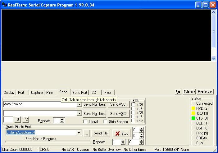
Lets see how to configure BLueLink-HC RS232 as MASTER Mode using RealTerm (click to download)
Note: Open RealTerm.Go to ‘Port’ option, set correct baudrate (38400) and assign correct port. Click ‘Change’ (encircled in green) to apply the changes. Now check the status of Port at the bottom of real term window(encircled in red). If it is closed, click ‘Open’ button (encircled in green) to open it.(In ‘Display’ option select Half Duplex so as to show outgoing characters in terminal)

By default all HC05 modules are SLAVEs. Using AT commands the module can be configured as we like.
- If you type in AT & click on Send ASCII button you should get an OK confirmation from the HC05 module.
- The ROLE of the module can be known by typing AT+ROLE? You can change it by AT+ROLE=0 ; 0 for SLAVE & 1 for Master. Leave it as 1 as we want this module to be MASTER.
- AT+CMODE=1; Allows connecting to any address.
Default is CMODE = 0 which allows connection to only bound address. - Initialize the SPP Profile library by typing; AT+INIT
If you get ERROR(17) , it means you’ve already issued this command & you can continue ignoring the error. - Start searching: inquire surrounding bluetooth devices AT+INQ. The format of the output is as follows:
+INQ:address,type,signal e.g. 19:A4:2C6A7,1F00,7FFF
Type can be ignored. The signal will be 7FFF since inquire is in standard mode.
Copy the address part of the devices found, for example 19:A4:2C6A7 and change the colons to commas – 19,A4,2C6A7 & click on Send ASCII button you should get an OK confirmation from module - And now to actually connect to the SLAVE ie; for data communiaction
AT+LINK=<address>
AT+LINK=19,A4,2C6A7
Click on Send ASCII button you should get an OK confirmation from module,now we can communicate in data communication mode.
Note: Each command is terminated with \r\n (ie 0x0d, 0x0a) corresponds to Carriage Return and Line Feed.

You can watch the status LEDs of both slave & master. After connection get establish LED glows.
Resources
- Software
- Data sheet
How to Buy?
- click here to buy rhydolabz BLueLink-HC RS232
- click here to buy rhydolabz USB To RS232 Converter- CP2102
Support
Please share your ideas with us, visit our forum for discussion
Frequently Asked Questions(FAQ):
Q. What if the voltage to the module rises?
Ans. Nothing happens because the voltage gets regulated automatically and is made within the permissible range.
Q. What is the role of LED’s in the module?
Ans. LED’s helps to indicate the status of BLueLink connection. Various stages of connection is clearly shown by the LED’s. It makes the user easy to solve the connection issues.
Leave a Reply
You must be logged in to post a comment.