PICkit™2 Programmer: Getting Started
PICkit2 Programmer is a low cost MPLAB Compatible PIC programmer. When connected, the MPLAB IDE detects it automatically. It can program PIC controllers operating at 3V3 and 5V.
 The PICkit2 Development Programmer/Debugger, a full featured Windows programming interface, supports baseline (PIC10F, PIC12F5xx, PIC16F5xx), mid rang (PIC12F6xx, PIC16F) ,PIC18F, PIC24, dsPIC30, dsPIC33,and PIC32 families of 8-bit, 16-bit, and 32-bit microcontrollers, and many Microchip Serial EEPROM products. With Microchip’s powerful MPLAB IDE (Integrated Development Environment), the PICkit 2 enables in-circuit debugging on most PIC microcontrollers. In-Circuit-Debugging runs and halts the program on break points while the PIC microcontroller is embedded in the application. When halted at a breakpoint, the file registers can be examined and modified. Using pickit2, we can use about 95% of the controller memory. If we use boot-loader to program, then we will have to reserve separate memory just to fuse boot-loader.
 Features
- USB Connection (cable Included)
- Automatic voltage switching (3V3 and 5V)
- Does not require external power supply
- 100% compatible with Microchip’s MPLAB IDE (Pickit2)
- Compact and handy design
- Both RJ11 connector and ICSP 6PIN Connector for programming.
- Supports PIC controllers operating at both 5V and 3V
Layout Getting Started
The PIC Programmer uses a USB port, for both powering and connecting to the computer, as opposed to the traditional serial port, eliminating the need for a separate power supply. It will automatically power the circuit, if the target controller is not powered. The programmer can be used to program 3.3V and 5V micro controllers. Automatic selection of voltage level is one of the unique features of this programmer.
PIN Description


- TARGET : The PIC Programmer Lite is powering the target device
- PWR : Power is applied to the PIC Programmer Lite via the USB port
- BUSY : The PIC Programmer Lite is busy with a function in progress, such as programming

Power up the PICKIT2 Programmer , PWR LED glows.
Selecting PICKIT2 Programmer as a Programmer tool
- Step 1: Launch MPLAB IDE,(click here to download)

- Step 2: The MPLAB IDE window opens as shown below

- Step 3: From MPLAB IDE menu bar select Configure >Select Device as shown below

- Step 4: Select the device to be programmed from the drop down list and click ‘OK’

- Step 5: Next from the menu bar select Configure >Configuration Bits

- Step 6: Now remove the ‘tick’ from Configuration Bits set in code and click ‘OK’ for the dialogue box appears as shown below

- Step 7: Set the ‘Setting‘ for the ‘Category’ as shown below and make sure the configuration Bits set in code is set or ‘tick’ marked.

- Step 8: From menu bar select Programmer > Select Programmer > PICkit 2 as shown below. When we select the option PICkit 2 from Programmer, in PICKIT2 Programmer target LED will glow. If the PICKIT2 Programmer didn’t connect automatically when it was selected as a Programmer tool, select Programmer > Connect to connect now. The connection status will be visible in the output window.

- Step 9: MPLAB will add PICkit 2 debug features: (A) the status bar will show PICkit 2 as the debug tool, (B) the programmer menu will change to add PICkit 2 functions and (C) the output window will display the communication status between the PICKIT2 Programmer and the target board on the PICkit 2 tab. Depending on the version of the MPLAB IDE software or the selected device, a message may appear indicating that the firmware (PICkit 2 operating system) needs to be updated. MPLAB IDE will automatically install new firmware.

- Step10: Import a compiled program (hex file) to program the target device by selecting File>Import

- Step 11: Load a hex file from desired folder

- Step 12: Click over the icon to program the target device as shown below. In PICKIT2 Programmer the BUSY LED glows at the time of programming.

- Step 13: When the program gets loaded successfully, the window will be as shown below

Now disconnect PICKIT2 programmer. The controller can be used for the desired application.
Selecting PICKIT2 Programmer as a Debug tool
- Step 14: Repeat steps 1 to 7 if user is getting started to use PICKIT2 Programmer as a Debug tool from start up of MPLAB IDE

- Step 15: Create a project in MPLAB IDE, complete the code, save it using .c extension and build the code as shown below. A hex file will be automatically generated.
Note: if you import a file from File > Import, rather than creating and building the code, then the debugger will debug the imported file

- Step 16: From menu bar Select Debugger > Select Tool > PICkit 2. if PICKIT2 is not automatically detected, when selected as debug tool, select Debugger > Connect to establish connection. The connection status will be visible in the output window.

- Step 17: MPLAB IDE will add PICkit 2 debug features: (A) the status bar will show PICkit 2 as the debug tool, (B) PICkit 2 debug tool will be added, (C) the Debugger menu will change to add PICkit 2 debug functions [as shown in Step 3], (D) the output window will display communication status, between the PICKIT2 Programmer and the target, on the PICkit 2 tab. Depending on the version of the MPLAB IDE and the selected device, a message may pop up, indicating that the firmware (PICkit 2 operating system) needs to be updated. MPLAB IDE will automatically install the new firmware.

- Step 18: Now click the icon (marked red in the image below) to Program the target device. On clicking the icon, the BUSY LED on the PICKIT2 Programmer glows; indicating that the debug mode is on.

- Step 19: To start debugging the code, mark a break point in the c file and click the icon (shown in the image below) to run the code.

- Step 20: Once the debug process is completed successfully, a green arrow will be displayed over the breakpoint. The output window will display the run and halt log for the target

PICkit 2 : Programmer-To-Go Mode
The PICkit 2 Programmer-To-Go functionality allows a PIC MCU memory image to be downloaded (.hex extension) on to the PICkit eeprom memory. The Programmer to go functionality doesn’t require any software or PC for programming. A USB power source for the PICkit 2 is all that is needed, connect the USB source to PICkit2 and the PWR LED will glow. Now follow the steps given below.
Step 1: PICkit 2 Programmer opens as follows,(click here to download)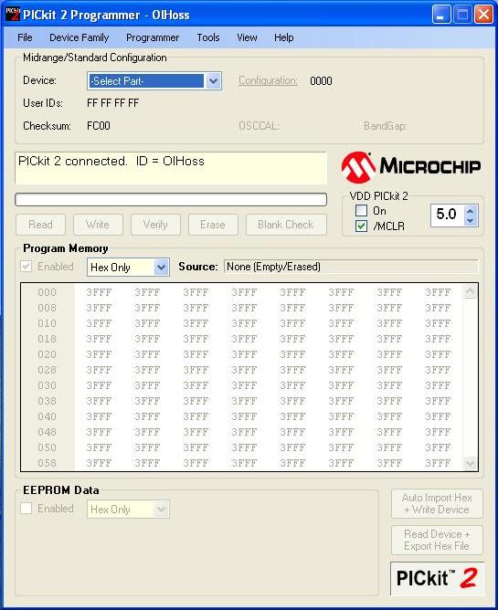 Step 2: Select the Programmer and set the options given below
- Programmer >Verify on Write
- Programmer >Hold Device in Reset
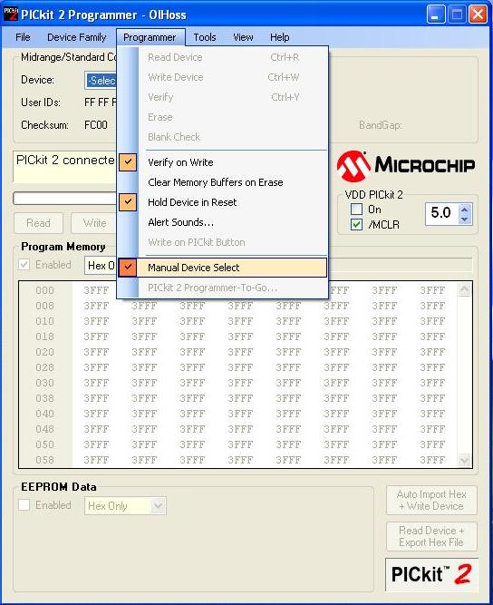
- Programmer >Manual Device Select
Step 3: Select the device from the drop down list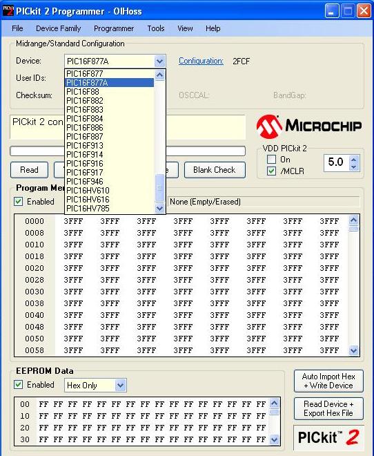 Step 4: Import the hex file from File > Import Hex
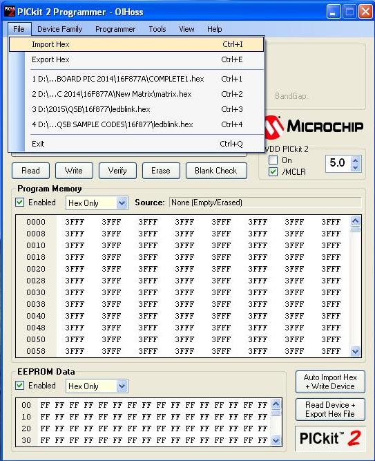 Step 5: A small window opens up, select the hex code of the bootloader program(or hex code of required program) from the window and click ‘open‘
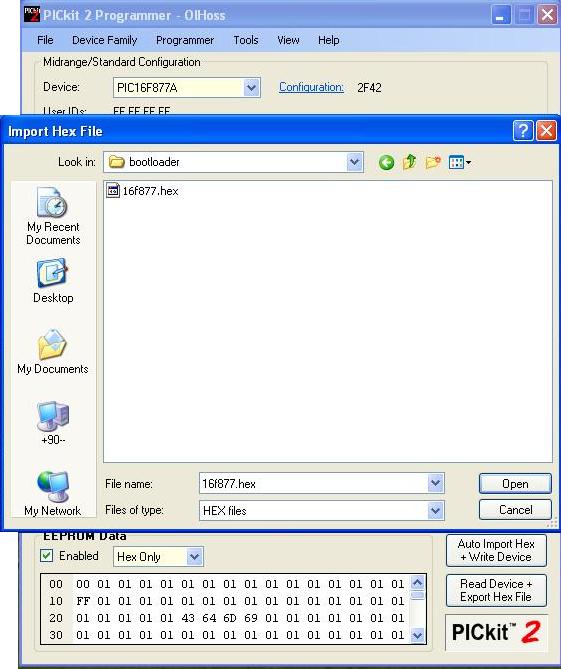 Step 6: The path can be viewed in Source .Once loaded, window displays hex file successfully imported as shown below
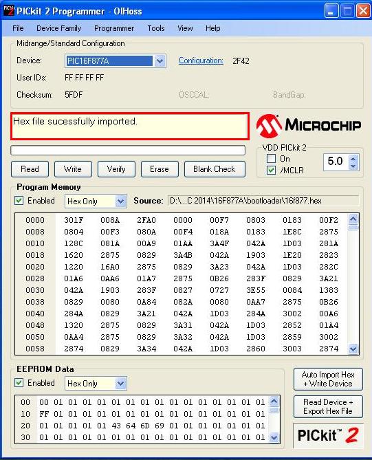
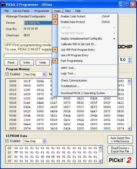
Step 7: Select the Tool and set the following options.
- Tools >Enable Code Protect
- Tools >Enable Data Protect
- Tools >Use VPP First Program Entry
- Tools >Fast Programming
The “VDD PICkit 2” device VDD box determines the provided VDD voltage (when the device is powered from PICkit2).
 Step 8: After setting the Tools options it will be displayed shown in the image below
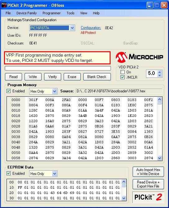 Step 9: Once the memory image and programming options for intended target device are set up and tested, start the Programmer-To-Go Setup Wizard via Programmer > PICkit 2 Programmer-To-Go…
 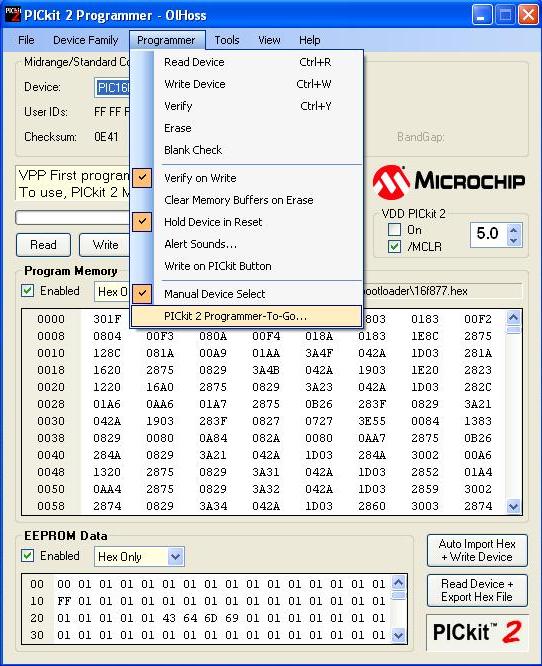 Step 10: The wizard dialog box opens up with a welcome screen. Click Next to go to the “Programmer Settings” screen.
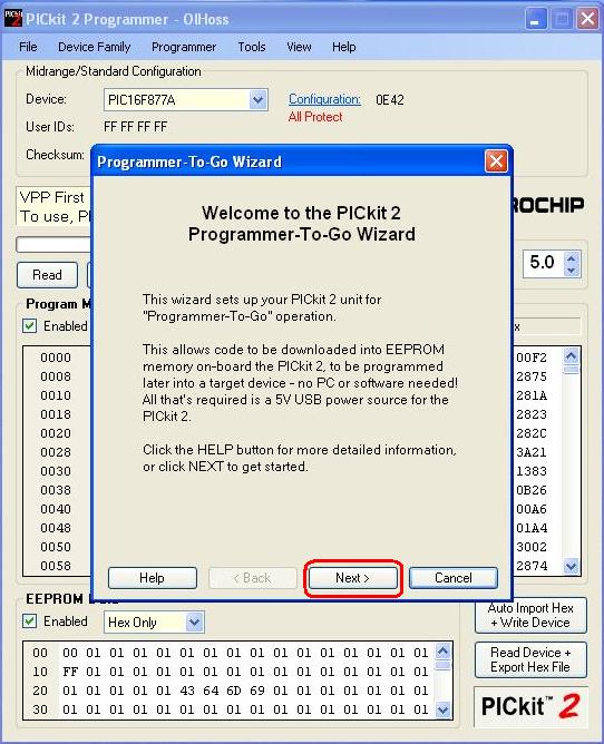 Step 11: The Programmer Settings screen allows the user to verify the memory image buffer settings, and also to select the target VDD power options to be used. Check it and click ‘Next‘.
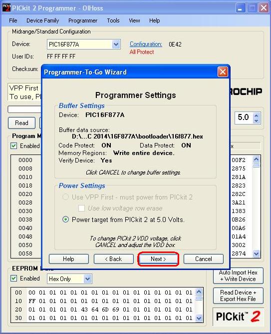 Step 12: Now the “Programmer to go-Wizard” window will provide a summary of the settings from the previous window, indicating whether the “Tools >Fast Programming and Programmer >Hold Device in Reset” are enabled or not. For most situations, both these options should be enabled. Click the Download button to store the memory image and settings in the PICkit 2 unit and place it in Programmer-To-Go mode.
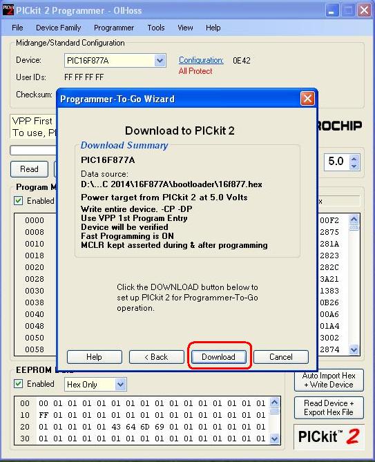 Step 13: When we go for Download operation the PICkit 2 “Busy” LED will remain lit continuously. The “Target” LED should now be blinking twice in succession to indicate that the PICkit2 is in Programmer-To-Go mode and it is ready to program. Disconnect the PICkit 2 from the PC USB port. When any USB power source is applied, the PICkit 2 unit will power up in Programmer-To-Go mode and “Target” LED will blink. Click Next to view the wizard screen with examples of Programmer-To-Go error codes, or click Exit to close the Wizard dialog box.
 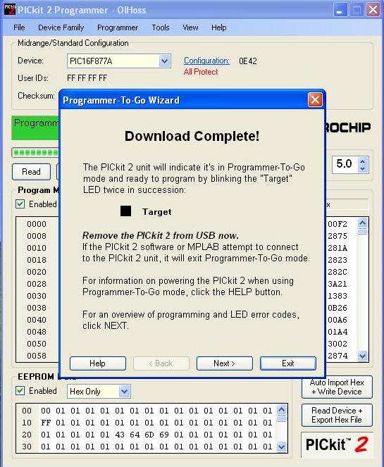 Step 14: Here we have opted for the ‘Next’ button, just to show you what will happen next, and a window appears with programming & error code examples as shown below.
 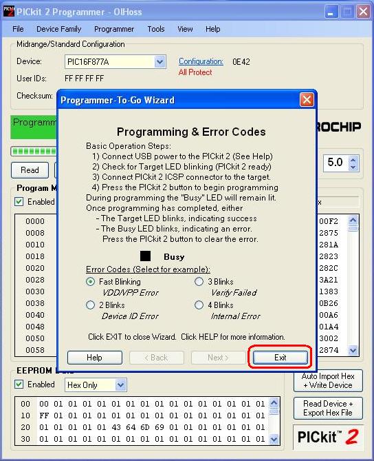 Step 15: To use PICkit 2 Programmer-To-Go to program a target device once it has been set up, follow the steps below.
- Connect a USB power source to the PICkit 2 unit,and also power up the target unit seperately.
- Ensure the PICkit 2 “Power” LED is lit,and the “Target” LED is blinking twice in succession to indicate the unit is in Programmer-To-Go mode and ready to program.
- Connect the PICkit 2 unit ICSP connector to the target. Ensure that the target is powered properly.
- Press the PICkit 2 pushbutton to begin programming.
During the programming operation the PICkit 2 “Busy” LED will remain lit continuously. The “Target” LED will be lit if the target is powered from PICkit 2, and otherwise not. When the programming operation is complete, the PICkit 2 unit will provide feedback on the operation via the unit LEDs.
Using PICkit2 to retrieve a program from the controller
Step1: Using MPLAB connect the target as programmer
[ Programmer > Select Programmer > Pickit 2 / Programmer > Connect ].
Then read the program as Programmer > Read or click icon, the output window displays as shown below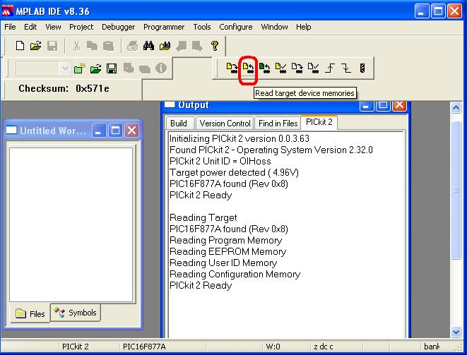 If necessary read the EEDATA memory as Programmer > Read EEDATA or click icon, the output obtained as shown below
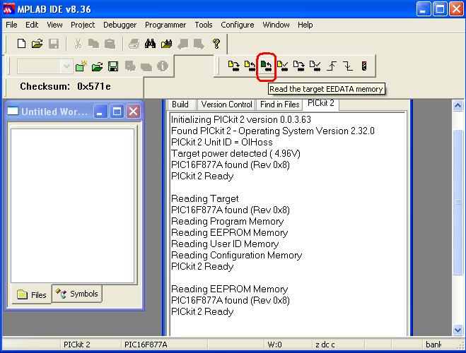
Step2: When PICkit 2 is ready to read, export the file File < Export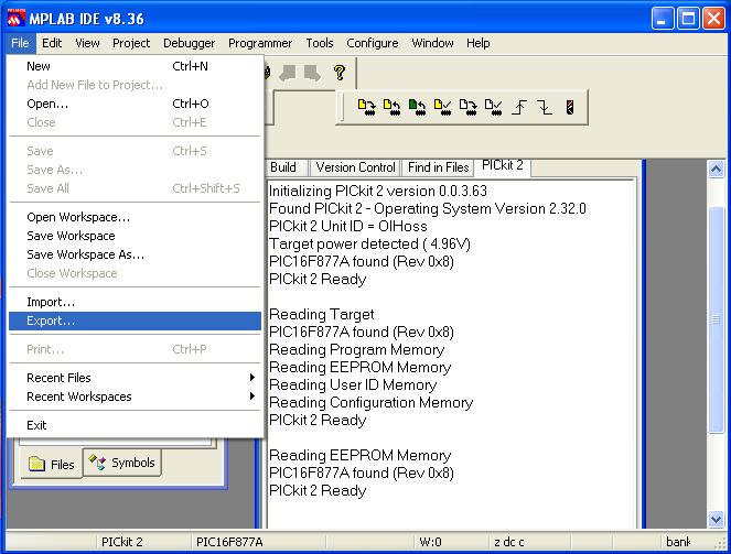
Step3: A small window opens as shown below, in this mark the necessary options and click ‘OK‘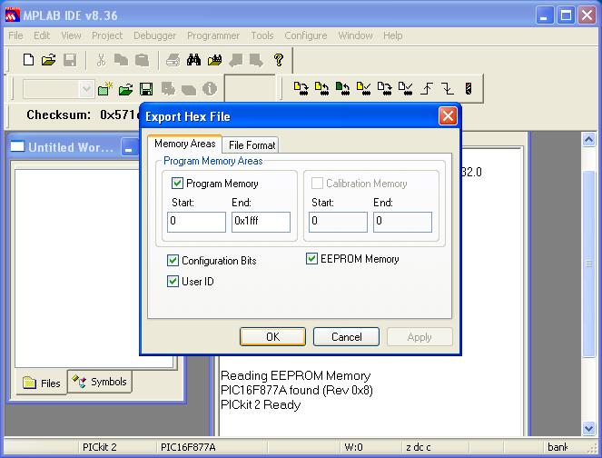
Step4: Save the hex file in a desired folder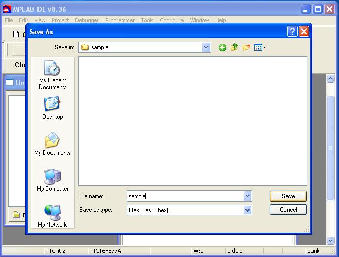
Step5: Thus retrieve the hex file from the controller, now use it for desired purpose.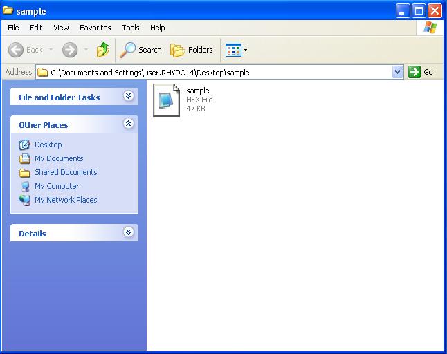
Resources
- Softwares
- Resources
How to Buy:
- Click here to buy PICKIT2 Programmer
- Click here to buy PIC Programmer Lite(MPLAB Compatible)
Support
- Please share your ideas with us, visit our forum for discussion
- If you a rhydoLABZ customer you contact our helpdesk
Frequently Asked Questions (FAQ)
Q.Does PICKIT2 Programmer have got EEprom in it ?
Ans.Yes. the PICKIT2 Programmer supports EEPROM in it.
Q.Is it possible to use PICKIT2 Programmer as a debugger?
Ans.Yes. PICKIT2 Programmer can be used as a programmer and a debugger
Leave a Reply
You must be logged in to post a comment.