Getting Interfaced With GSM/GPRS TTL UART MODEM-SIM900
A modem is a device that modulates an analog carrier signal to encode digital information, and also demodulates such a carrier signal to decode the transmitted information. .
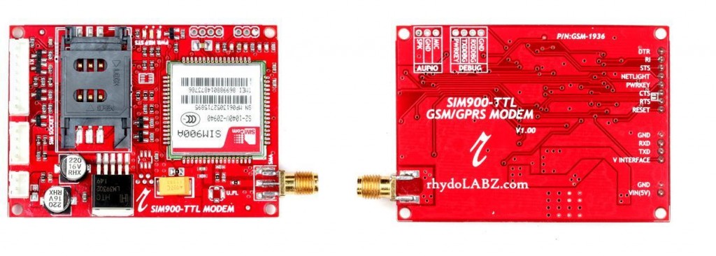
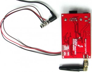
RhydoLABZ’s GSM/GPRS TTL UART Modem is built with Quad Band GSM/GPRS engine- SIM900, works on frequencies 850/ 900/ 1800/ 1900 MHz. The Modem is coming with selectable interfacing voltage,which allows you to connect 5V & 3V3 microcontroller directly without any level conversion chips. The baud rate is configurable from 9600-115200 through AT command. The GSM/GPRS Modem is having internal TCP/IP stack to enable you to connect with internet via GPRS. It is suitable for SMS, Voice as well as DATA transfer application in M2M interface.
The Modem is manufactured with Automatic Pick and place machine with high quality standard.The onboard Low dropout 3A Power supply allows you to connect wide range unregulated power supply (5V-12V) . Using this modem,you can make audio calls, SMS, Read SMS, attend the incoming calls and internet etc through simple AT commands.
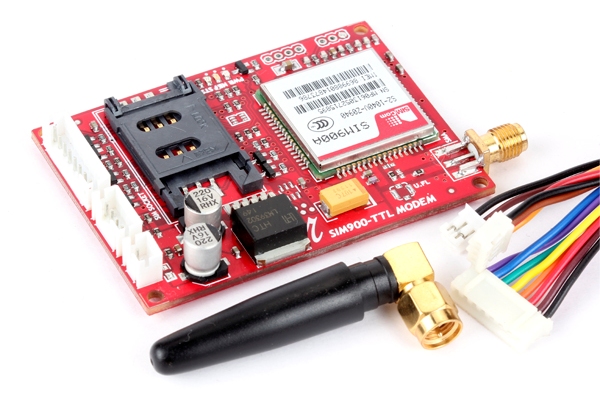
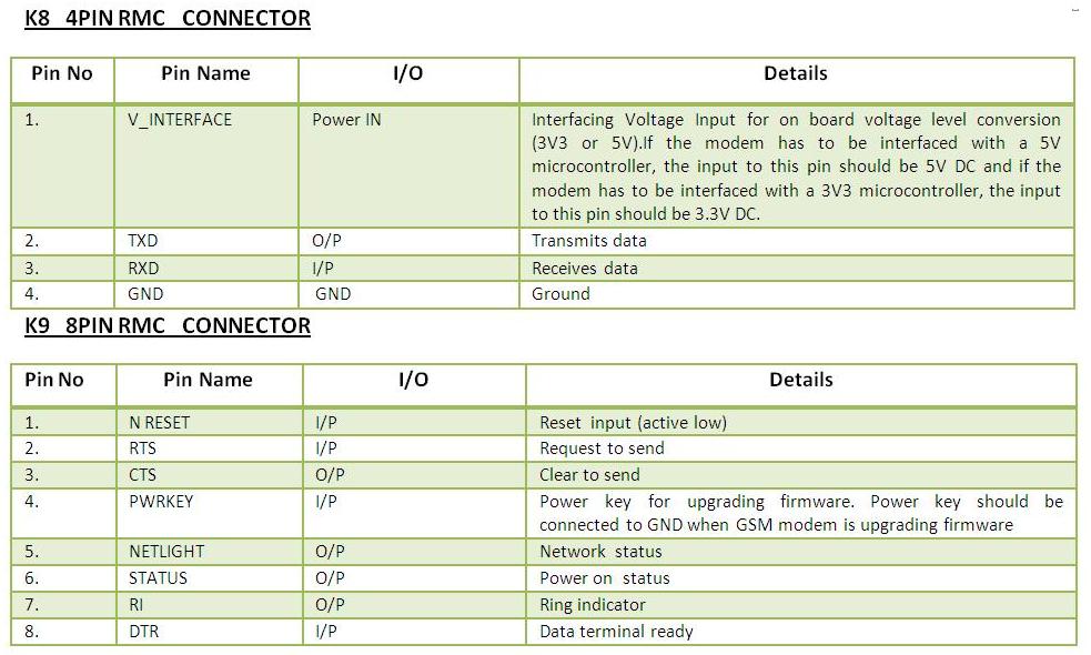
This modem can operate at both TTL 3.3V and 5V Logic Level hence making it suitable for controllers at 5V logic level (PIC, AVR) as well as for 3.3V controllers like ARM based controllers and while interfacing depending upon the controller’s logic level we should give appropriate voltage to the V_interface pin of the modem like 3.3V or 5V(should be in the range 2.5-6V) and power the modem with supply range(5V-12V).
The SIM900 is a complete Quad-band GSM/GPRS solution in a SMT module which can be embedded in the customer applications. Featuring an industry-standard interface, the SIM900 delivers GSM/GPRS 850/900/1800/1900MHz performance for voice, SMS, Data, and Fax in a small form factor and with low power consumption. With a tiny configuration of 24mm x 24mm x 3 mm, SIM900 can fit almost all the space requirements in your M2M application, especially for slim and compact demand of design.
Note:SIM900 can be used worldwide.GSM-900 Bands and GSM-1800 Bands are used in most parts of the world: Europe, Middle East, Africa,Australia, Oceania (and most of Asia).GSM-850 Bands and GSM-1900 Bands are used in Canada, the United States and many other countries in the Americas.
Features:![]()
- High Quality Product (Not hobby grade)
- Quad-Band GSM/GPRS 850/ 900/ 1800/ 1900 MHz
- 3V3 & 5V interface for direct communication with MCU kit
- Configurable baud rate
- SMA connector with GSM Antenna.
- SIM Card holder.
- Built in Network Status LED
- Inbuilt Powerful TCP/IP protocol stack for internet data transfer over GPRS.
- Audio interface Connector
- Normal operation temperature: -20 °C to +55 °C
- Input Voltage: 4.5V-12V DC
Pin diagram:![]()
Pin details:![]()
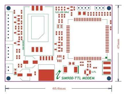
Layout:![]()

- Make sure your SIM card is unlocked.
- Default factory baudrate is 9600.
- Input Voltage: 4.5V-12V DC.
Getting started:![]()
- Insert an unlocked SIM card to SIM card Holder. 6 Pin Holder for SIM Cards is provided on the Modem.
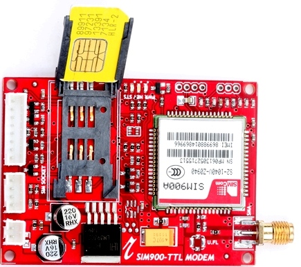
- Close SIM card Holder.Both 1.8 volts and 3.0 volts SIM Cards are supported by SIM900 – the SIM card voltage type is automatically detected.
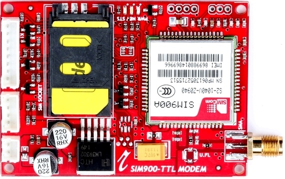
- Assemble GSM Antenna to the modem
- Connect serial cable to the modem .
- Give power supply in between 4.5V to 12V through the power jack provided
- Default factory Baudrate is 9600
- When the modem is successfully powered-up, the Red LED on the modem (PWR) will be ON, the STS LED (GREEN) will light after 1-2 seconds and the NET LED(BLUE) will blink every second. After the Modem registers in the network (takes between 10-60 seconds), this LED will blink in step of 3 seconds.
LED status description:![]()
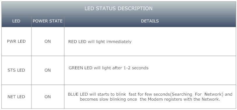
The Network LED indicates the various status of GSM module eg. Power on, Network registration & GPRS connectivity. When the modem is powered up, this NETWORK LED will blink every second. After the Modem registers in the network (takes between 10-60 seconds), this LED will blink in step of 3 seconds. At this stage you can start using Modem for your application,showing that modem is registered with the network.
How to test:![]()
1. Check your GSM/GPRS Modem Using Hyper terminal in PC:
- For making a connection between GSM/GPRS TTL UART MODEM-SIM900 and PC you need RS232 – TTL (5V) Converter or you can use FTDI Basic Breakout – 5V.
- Before making connection with the system you should give external supply to the modem (4.5v-12v DC) and make the ground of this supply common with GND of modem and the converter.This should be done because we cannot power the modem from the USB supply as normal operation of the modem requires a minimum current of 590 mA so its better to use a power source with 1-2A current rating
- One sample test is shown using rhydoLABZ GSM/GPRS TTL UART MODEM-SIM900. For making connection with PC we are using rhydoLABZ FTDI Basic Breakout-5V.
- Firstly install a virtual serial port loading on the computer FT232RL drivers. Once the drivers are installed, connect the modem, with USB/mini-USB cable, and wait while it is found and that mean drivers are actually installed.
- The connection details of rhydoLABZ GSM/GPRS TTL UART MODEM-SIM900 with rhydoLABZ FTDI Basic Breakout-5V is as shown below.
- Connections should be like below :
- TX(modem)-RX(converter TTL)
- RX(modem)-TX(converter TTL)
- Make ground (GND-GND)common.
- Many embedded devices communicate over the serial port connection as most modern computers lack a hardware serial port;USB adapters are used to convert USB data to standard serial port data and vice versa.
- For a quick tutorial on FTDI Basic Breakout – 5V and connection details please Go through the link.
- Once you are done with all these procedures, choose the appropriate COM port that got assigned to the USB in your system by looking into the device manager like as shown below.
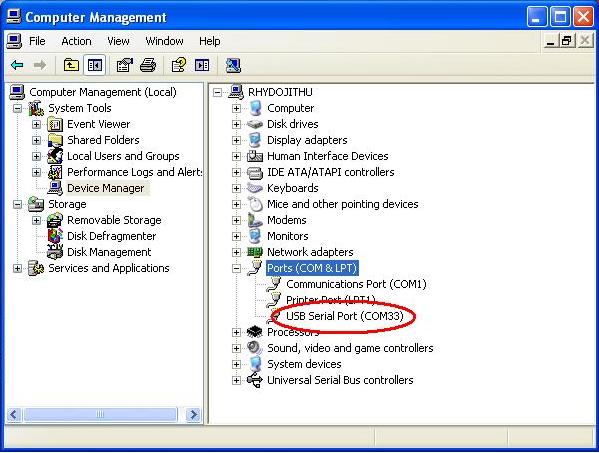
- In case we are having window XP OS and not having window terminal in it, then we need to create a new window terminal for checking our Modem using PC.
Creating a Hyperterminal
- If you are using Windows XP, you can create a new Hyperterminal as shown below:
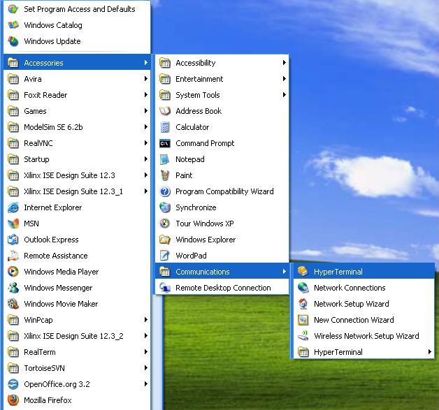
- There could be some windows as shown below ,You may set and skip as per the highlights:


- Now you can give an appropriate name to the connection like 9600 and click OK.

- Also Select the appropriate COM port when asked for, in our case most probably it would be COM1.
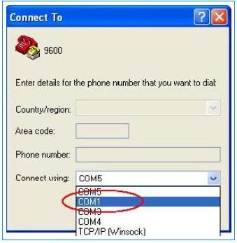
- Ensure that you have kept the settings like Baud rate which should be 9600, parity none ,data bits 8 and stop bit 1 and flow control can also be kept as none.
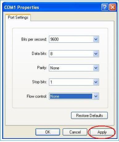
- You can simply use Hyper Terminal. After you click apply and OK you will be shown the window below,By default it would be disconnected, Simply Click on the Highlighted button to connect.
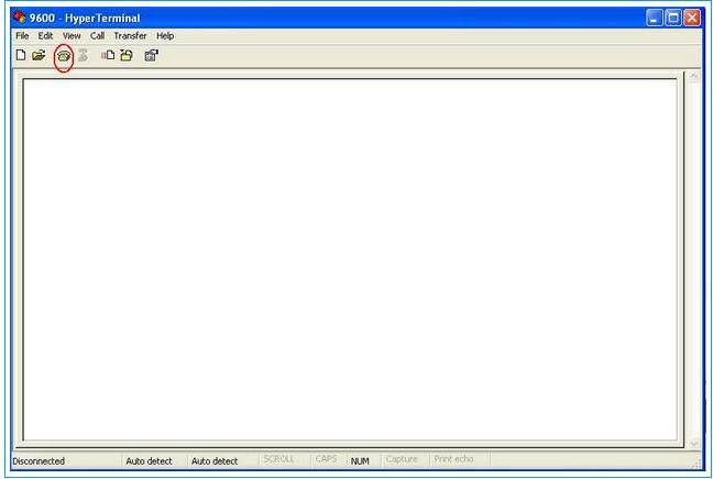
- Now let’s try to check our Modem with AT commands for that we need to send following AT commands to Modem as shown below.
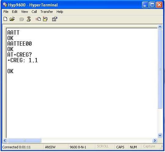
- The above shown command :AT command (followed by enter) after “OK” response, this signifies that our Modem is working properly.ATE0 command (followed by enter) is being sent to stop the echo. AT+CREG? (followed by enter) is being used to check whether the SIM got registered or not.
- To get complete application note on AT commands click here.
Sending a text message from PC using AT Commands and Hyperterminal
- Now next let’s send a message using rhydolabz GSM/GPRS TTL UART SIM900. For sending message we need to first send related AT commands to initialize the modem to send a message.
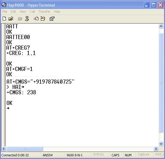
- The AT+CMGF=1 command (followed by enter) sets the GSM Modem in SMS text mode.
- AT+CMGS=<number>followed by enter gives<CR><write message><Ctrl+z>
<CR> represents the carriage return character.
<Ctrl+z>When you finish entering the SMS message body, you have to enter the <Ctrl+z> character to mark the end of the SMS message body.
+CMGS: x and OK; where x = “current number of sent SMS messages”
Receiving a text message in Modem and displaying in Hyperterminal window
- Now let’s receive a message using rhydolabz GSM/GPRS TTL UART SIM900.For receiving message we need to first send related AT commands to initialize the modem.
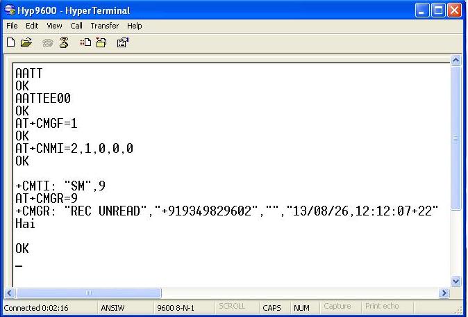
- AT+CNMI=2,1,0,0,0 command (followed by enter) set the modem to indicate received messages with +CMTI response indicates that new message has been received and shows location number of last received message in above figure it is shown by number ’9′.
- AT+CMGR=<index> :<index>integer type; value in the range of location numbers supported by the associated memory and gives +CMGR response which includes status i.e “REC UNREAD” Received unread messages,Sender’s number,date,time and received message.
Receiving a voice call from Modem using AT Commands
- For receiving call we need headset,connector jack and modem.
- Headset is connected in the marked pins of GSM Modem
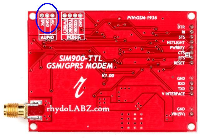
- Connections are as shown below
- Connect MIC of Modem to MIC of Jack
- Connect SPK of Modem to SPK of Jack
- Connect GND of Modem to GND of Jack
- For receiving a call firstly we need to send some AT commands as shown below.
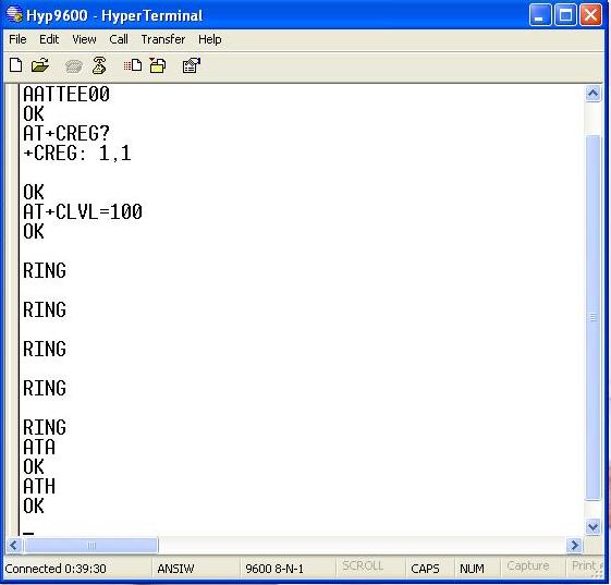
- Loudspeaker Volume Level
AT+CLVL=?
0..max – the value of max can be read by issuing the Test command
For example:
AT+CLVL=100 -Command is used to select the volume of the internal loudspeaker audio - RING indicates incoming call.
- For Attending call we are using ATA command (followed by enter) gives “OK” response when call is connected.
- For Disconnecting call we are using ATH command (followed by enter) gives “OK” response when call is disconnected.
Check your GSM/GPRS Modem Using Online AT Command Tester
- AT Command Tester is an online tool for testing AT commands and other module functionalities such as data call, voice call,HTTP, network registration, SMS, Phonebook, signal quality, SIM interface, device info etc.
- Firstly you need to connect your GSM Modem with your system.
- Here some example are shown using AT Command Tester
- First select ‘Find Ports’ to search for available ports. Then select the modem port and press ‘Connect’. Once connected to the module, you can send AT commands from the ‘Command Mode’ tab

- Sending AT commands using AT Command Tester

AT command (followed by enter) after “OK” response, this signifies that our Modem is working properly.ATE0 command (followed by enter) is being sent to stop the echo.
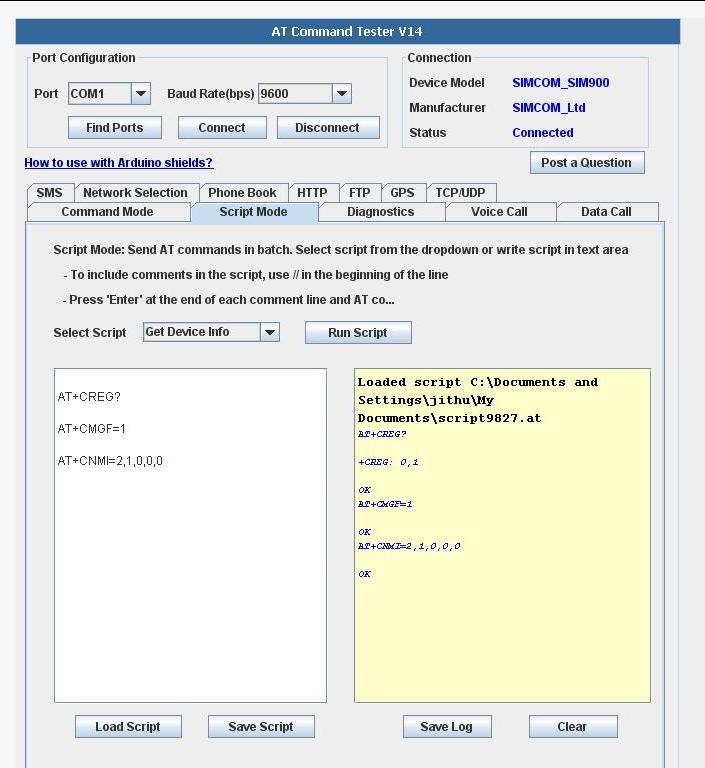
- In script mode, you can send multiple AT commands at a same time as shown below. You can create your own script and save it on the local machine.Then load the script and execute.

- In script mode we can save necessary AT commands and if required than we just need to load that saved script and by clicking on Run Script we will get output in column provided at right side of the tester.
- For saving script click on save script (in right side column its shown where your script got saved) as shown below

- For loading script click on load script (in right side column loaded script path is shown) then click on Run Script and output is as shown below in right column.
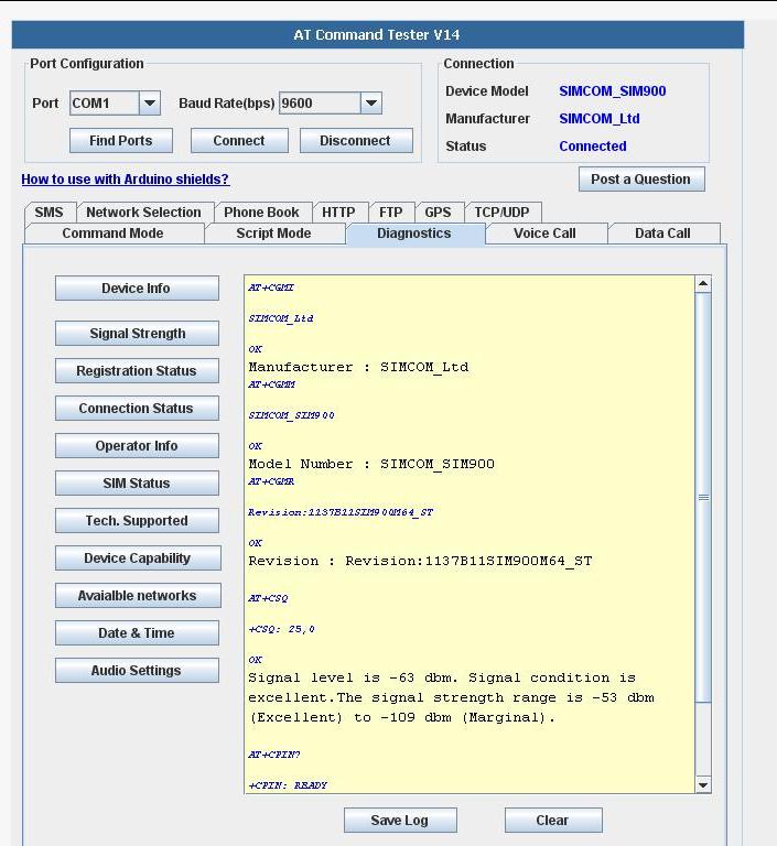
- To perform basic diagnostics on the SIM900 module, choose the ‘Diagnostics’ tab.
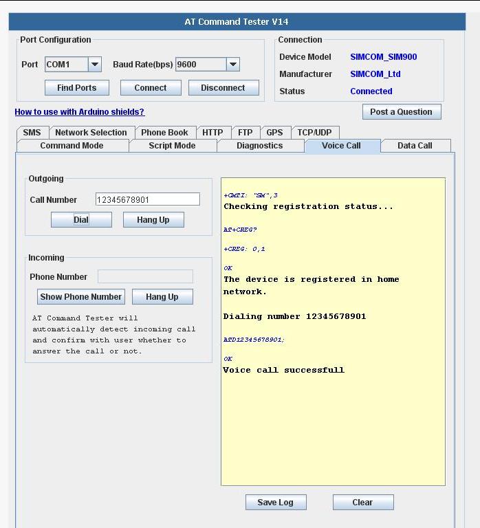
- Select the ‘Voice Call’ tab to test outgoing and incoming voice calls.The ‘AT Command Tester’ will check whether the device is registered before dialing the call.
- Select the ‘SMS’ to send SMS messages. You can also read and delete SMS messages stored on the SIM.

2.Test with Arduino
- Sample code below shows how we can send a message using Arduino interfacing with modem
|
1 2 3 4 5 6 7 8 9 10 11 12 13 14 15 16 17 18 19 20 |
void setup() { Serial.begin(9600); // set the baud rate } void loop() { Serial.print("AT\r\n"); // Transmit AT to the module delay(500); // wait for a 500ms delay Serial.print("ATE0\r\n"); // Echo Off delay(500); // wait for a 500ms delay Serial.print("AT+CMGF=1\r\n"); // Switch to text mode delay(500); // wait for a 500ms delay Serial.print("AT+CNMI=2,1,0,0,0\r\n"); // Msg:settings command delay(500); // wait for a 500ms delay Serial.print("AT+CMGS=\"919874563210\"\r\n"); // Send SMS to a cell number delay(500); // wait for a 500ms delay Serial.print("\rTest SMS from rhydoLABZ.com-Cochin\r\n"); // Input SMS Data Serial.print('\x1A'); // Ctrl-Z indicates end of SMS delay(500); // wait for a 500ms delay while(1); } |
3.Testing With PIC16f877
- Interfacing of GSM Modem with PIC 16F877A is shown below.
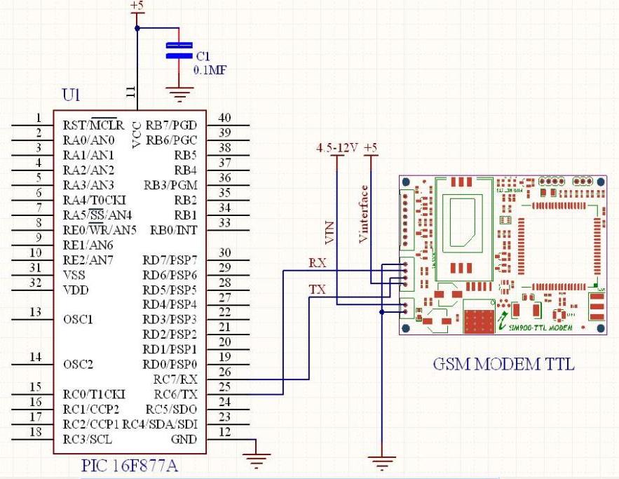
- Sample code below shows how we can send a message using PIC 16F877A interfacing with modem
|
1 2 3 4 5 6 7 8 9 10 11 12 13 14 15 16 17 18 19 20 21 22 23 24 25 26 27 28 29 30 31 32 33 34 35 36 37 38 39 40 41 42 43 44 45 46 47 48 49 50 51 52 53 54 55 56 57 58 59 60 61 62 63 64 65 66 67 68 69 70 71 72 73 74 75 76 77 78 79 80 81 82 83 84 85 86 87 88 89 90 91 92 93 94 95 96 97 98 99 100 101 102 103 104 105 106 107 108 109 110 111 112 113 114 115 116 117 118 119 |
/******************************************************************************* * Microcontroller -- PIC 16 F877 - 40-pin - 8-bit * * Clock Frequency is 20 MHz -- Period in 200 Nano Seconds * * Gsm communications are done using USART - BaudRate 9600 * * This program sends an SMS to a prefixed number when reseted. * *******************************************************************************/ #include<pic.h> /******************************************************************************* * FUNCTION DEFINITIONS *******************************************************************************/ void Delay_Ms(int ms); void Uart_Initial_Tx_Rx(unsigned long baud); void Uart_Data(unsigned char data); void Send(const char *ptr); void Send_Message(); /******************************************************************************** * CODE AREA ********************************************************************************/ void main() { Uart_Initial_Tx_Rx(9600); Send_Message(); while(1); } /******************************************************************************* * Function : Uart_Initial_Tx_Rx * Description : Usart Initialization function - Baud Rate 9600 * Parameters : baud, for selecting baurd rate *******************************************************************************/ void Uart_Initial_Tx_Rx(unsigned long baud) { TRISC6 = 0; /* Set Tx pin Output and Rx pin Input */ TXEN=1; /* Transmit Enabled */ BRGH=1; /* BaudRate = 9600 */ SYNC=0; /* Asynchronous Mode */ SPEN=1; /* Enable Serial Port */ if(baud == 9600 ) SPBRG = 129; else if (baud == 19200) SPBRG = 64; else if (baud == 38400) SPBRG = 32; else if (baud == 57600) SPBRG = 21; else if (baud == 115200) SPBRG = 10; } /******************************************************************************** * Function : Uart_Data * Description : Function to send data through the UART * Parameters : data, contains the data to be transmitted and is written to * the TXREG register ********************************************************************************/ void Uart_Data(unsigned char data) { TXREG=data; while(TRMT!=1); } /******************************************************************************** * Function : Send * Description : Function to send a string data thru USART * Parameters : ptr, contains the byte to be sent ********************************************************************************/ void Send(const char *ptr) { while(*ptr!='\0') { TXREG=*ptr; while(TRMT!=1); ptr++; } } /******************************************************************************** * Function : Delay_Ms * Description : Function for milliseconds at 20mhz * Parameters : ms, variable for delay ********************************************************************************/ void Delay_Ms(int ms) { int i,count; for(i=1;i<=ms;i++) { count=498; while(count!=1) { count--; } } } /******************************************************************************** * Function : Send_Message * Description : Function to send commands for sending sms * Parameters : None ********************************************************************************/ void Send_Message() { Send("AT\r\n"); /* Transmit AT to the module */ Delay_Ms(500); /* 500ms delay */ Send("ATE0\r\n"); /* Echo Off */ Delay_Ms(500); /* 500ms delay */ Send("AT+CMGF=1\r\n"); /* Switch to text mode */ Delay_Ms(500); /* 500ms delay */ Send("AT+CNMI=2,1,0,0,0\r\n"); Delay_Ms(500); /* 500ms delay */ Send("AT+CMGS=\"919874563210\"\r\n"); /* Send SMS to a cell number */ Delay_Ms(500); /* 500ms delay */ /* Input SMS Data */ Send("\rTest SMS from rhydoLABZ.com-Cochin\r\n"); Uart_Data(0x1A); /* Ctrl-Z indicates end of SMS */ Delay_Ms(500); /* 500ms delay */ } /******************************** END ******************************************/ |
Resources:![]()
- SIM900 AT Command Set
- GSM Modem UART TTL User Manual
- SMS Sending Software ( Windows)
- SMS Application Note
- TCP/IP Application Note
How to Buy:![]()
- Click here to buy GSM/GPRS TTL UART MODEM-SIM900
- Click here to buy FTDI Basic Breakout – 5V (rhydoLABZ).
Support:![]()
- Please share your ideas with us, visit our forum for discussion.
Frequently Asked Questions(FAQ):![]()
Q. What is the operating voltage range ?
Ans: Input voltage given to the module is from 5V-12V.
Q. Why Antenna is needed in GSM modem ?
Ans: Antenna is needed to increase gain level,to establish a communication.
Q. Why sometimes we are not able to hear properly in Headset connected to the modem ?
Ans: This problem arises because some times we forget to set loudspeaker volume.
loudspeaker volume is set by following AT command
AT+CLVL=?
0..max – the value of max can be read by issuing the Test command
For example:
AT+CLVL=100 -Command is used to select the volume of the internal loudspeaker audio.
Q. What the three LEDs indicate in the GSM modem ?
Ans: PWR LED(Power LED) – Red LED will lit immediately
STS LED(Status LED) – Green LED will lit after 1-2 seconds
NET LED (Network LED) -Blue LED will blink fast for few seconds(Searching For Network) and becomes slow blinking once the Modem registers with the Network.

Leave a Reply
You must be logged in to post a comment.