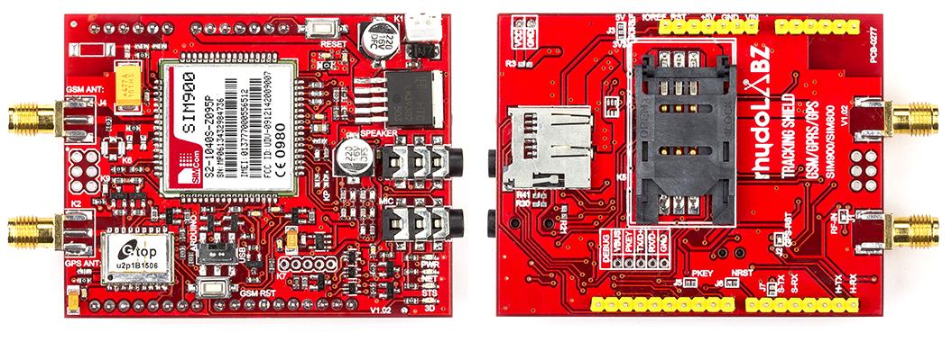
Familiarize with rhydolabz Tracking Shield (SIM800 / SIM900 / SIM900A)
An all-in-one arduino compatible shield from rhydoLABZ, that lets you add location-tracking, voice, text, data connectivity and data storage to your project in an adorable little package. The shield features new generation GlobalTop GPS chipset and SIM800/900/900A. With GPS technology, the shield supports satellite navigation along with cellular connectivity and that makes most of what you need for your robotics projects.
GSM/GPRS connectivity is controlled via AT commands, while the GPS functionality follows NMEA protocol. The shield also offers data storage on microSD card. The design of this shield allows you to drive the GSM module directly with the computer as well as with your Arduino Board. The package includes duck type SMA antenna for cellular network connectivity and an active external antenna for GPS functionality. GPS U2P module offers a high sensitivity, incredibly low power consumption while searching with -165dBm high sensitivity and 10Hz maximum update rate. Featuring an industry-standard interface and GPS function, the combination of both technologies on a single shield allows items, vehicles and people to be tracked seamlessly at any location and anytime with signal coverage.
 Features
![]()
- AT command interface
- Quad-band (SIM900 and SIM800) and Dual-band (SIM900A) variants
- Make and receive voice calls
- Send and receive SMS messages
- Send and receive GPRS data (TCP/IP, HTTP, etc.)
- Inbuilt Powerful TCP/IP protocol stack for Internet data transfer over GPRS
- Bluetooth (for SIM800 only) : compliant with 3.0 + EDR
- Debug Connector for GSM firmware updation
- Standard Flap type SMA Socket
- ESD Protection over TVS Zener array
- Configurable Baud rate (factory default value: 9600)
- Standard Audio Jack Connectors for external speaker and mic
- Level shifting circuitry to make it Arduino-safe
- SMA connectors to connect external antennas for GSM & GPS
- Indicator LEDs for Power, Netlight, Status and 3D Fix
- GlobalTop U2P GPS with MediaTek MT3339 Chipset
- MMC card slot for data storage
- GSM module communicates via hardware serial pins
- GPS module communicates via software serial pins
- S-TX – digital pin 5
- S-RX – digital pin 4
- Separate Reset switches for both Arduino and the GSM module
- Slide switch to swap the GSM module between Arduino and PC
- Supply Voltage : 7-12 V DC
- On-board 5V & 3.3V regulators
SIM900A, SIM900 & SIM800![]() SIM800 modules are upgraded version of its previous successful GSM/GPRS/GPRS module series SIM900. There are multiple sub versions of each series, each of which cater to a different set of users and applications. SIM900 comes in the form of full version Quad band SIM900 & dual band version SIM900A. SIM800 itself is the full version Quad band SIM800. There are other SIM800 & SIM900 versions but very less information available about them, so they have not been discussed.
SIM800 modules are upgraded version of its previous successful GSM/GPRS/GPRS module series SIM900. There are multiple sub versions of each series, each of which cater to a different set of users and applications. SIM900 comes in the form of full version Quad band SIM900 & dual band version SIM900A. SIM800 itself is the full version Quad band SIM800. There are other SIM800 & SIM900 versions but very less information available about them, so they have not been discussed.
What extra does SIM800 modules give me compared to SIM900 series modules? SIM800 GSM modules have a inbuilt Bluetooth stack compliant, and the interface is accessible using AT commands.
SIM900 and SIM900A modules operate from 3.2V to 4.8V supply range while SIM800 modem operates from 3.4V to 4.4V supply range (Reduced operating range!). Same AT commands used for simple call/sms functionality in SIM900, SIM900A can be used with the SIM800, but SIM800 series have added AT command set for supporting extra features like bluetooth.
SIM800 module is needed only if you need those additional features that are not present in SIM900 series modules, like the Bluetooth connectivity which was missing in SIM900 series. SIM800 and SIM900 can be operated worldwide because they can operate in all four GSM bands used across the world.
Layout![]()
![]() LED Description
LED Description![]()
- PWR – Power indication, turns on when the shield is powered
- NET – Network status
- Off – Modem not running
- 64ms on/ 800ms off – Modem not registered to the network
- 64ms on/ 3000ms off – Modem registered to the network
- 64ms on/ 300ms off – GPRS communication is established
- STS – Indicates operating status of the module. LED is on when the module is powered.
- 3D – Blinks when GPS is not fixed, turns off when GPS is fixed
Jumper Description![]()
- J1(RF-IN) – Short J1 to use active antenna for GPS
- J2 – Short to connect GPS RST to digital pin 6 of Arduino
- J3 – Selects IOREF as 3.3 / 5 V
- J4 – GSM Antenna connector
- J5 – Short to connect PKEY to digital pin 8 of Arduino
- J6 – Short to connect GSM RST to digital pin 7 of Arduino
- J7 – Short to connect GPS RX to S-TX (digital pin 5) of Arduino
Connector Description![]()
- K1 – Power Supply
- K2 – GPS Antenna connector
- K3 – Speaker Jack
- K4 – MIC Jack
- K5 – SIM Socket
- K6 – Provision for U. FL antenna connector
- K7 – GSM debug
- K8 – SD card socket
- K9 – Arduino ICSP
Switches![]()
- SW1 – DPDT slide switch to swap the shield between Arduino and PC. The shield communicates with Arduino / PC as selected by the switch
- SW2 – Arduino Reset
- SW3 – GSM Reset
PKEY using Arduino
PWRKEY pin of GSM modem is to turn modem On/Off externally using open collector transistor or switch. You can turn on/off the modem alternately by driving the PWRKEY to a low level voltage for a short time (2-3 sec) and then release. This pin is pulled up to 2.9V in the GSM Modem.

In the shield, it is connected to digital pin 8 of Arduino via jumper J5. Shorting the jumper and removing R16 from board enables you to power on /off the modem by Arduino.
GSM RST using Arduino
RST pin of GSM modem is active low. In the shield, it is connected to digital pin 7 of Arduino via jumper J6. Short J6 and make the pin 7 HIGH to reset the modem.
GPS RST using Arduino
Reset pin of GPS is active low. In the shield, it is connected to digital pin 6 of Arduino via jumper J2. Short J2 and make the pin 6 HIGH to reset the GPS.
Audio Jacks
The Shield contains two audio stereo jacks on board. The first is the audio input jack (labeled “MIC”). This allows you to input audio from any device such as an MP3 player, or cellular phone using a basic audio cable. The second audio jack is the audio output, labeled “SPEAKER”. This jack allows you to route the audio out to a speaker.
Micro SD Card![]() The shield also has a micro SD card socket to add external storage to your project. It communicates with Arduino using SPI protocol. You can directly use Arduino SD library that is available with Arduino IDE. Note that the library uses pin4 as Slave select whereas the shield uses pin9 for slave select, so you have to change your program accordingly.
The shield also has a micro SD card socket to add external storage to your project. It communicates with Arduino using SPI protocol. You can directly use Arduino SD library that is available with Arduino IDE. Note that the library uses pin4 as Slave select whereas the shield uses pin9 for slave select, so you have to change your program accordingly.
Getting Started![]() Lets check out on getting started with this shield on Arduino. What would be the first thing you want to do with it? Send out GPS cordinates as text (SMS)?
Lets check out on getting started with this shield on Arduino. What would be the first thing you want to do with it? Send out GPS cordinates as text (SMS)?
- Insert an activated SIM Card to the SIM Socket (K5), provided on the bottom side of the shield.
- Also insert a microSD card in the SD card slot
- Adjust the slide switch as per convenience
- USB – GSM modem communicates with the PC directly without an ATmega328 on your Uno,
- Arduino – GSM modem communicates with the ATmega328 on your Uno)
- Copy the given code and paste it in a new sketch on your Arduino IDE. Compile and burn it to your Arduino
- Before stacking the shield to your Arduino, let the SIM get registered to the network
- When GPS modem gets fixed (3D LED turns off), you will receive the GPS cordinates of your location as text message and also the same will be written to SD card as text file
|
1 2 3 4 5 6 7 8 9 10 11 12 13 14 15 16 17 18 19 20 21 22 23 24 25 26 27 28 29 30 31 32 33 34 35 36 37 38 39 40 41 42 43 44 45 46 47 48 49 50 51 52 53 54 55 56 57 58 59 60 61 62 63 64 65 66 67 68 69 70 71 72 73 74 75 76 77 78 79 80 81 82 83 84 85 86 87 88 89 90 91 92 93 94 95 96 97 98 99 100 101 102 103 104 105 106 107 108 109 110 111 112 113 114 115 116 117 118 119 120 121 122 123 124 125 126 127 128 129 130 131 132 133 134 135 136 137 138 139 140 141 142 143 144 145 146 147 148 149 150 151 152 153 154 155 156 157 158 159 160 161 162 163 164 165 166 167 168 169 170 171 172 173 174 175 176 177 |
#include <SoftwareSerial.h> #include <SPI.h> #include <SD.h> SoftwareSerial GPS(4,5); /* Software serial - RX, TX pins */ File Cordinates; /*........................................ Variables declaration ............................................. */ char Rec_data; char RMC_flag=0,comma=0,i=0,j=0; char latitude[12],longitude[12]; int smsflag=0,stable=0,finish=0,snd=0; /*............................................... Setup ....................................................... */ void setup() { Serial.begin(9600); /* Initialize serial communication at 9600 bits per second */ GPS.begin(9600); /* Initialize software serial at 9600 bps for GPS */ while (!SD.begin(9)) { Serial.println("SD Card Initialization failed!"); return; } Serial.println("SD Card Initialized"); Serial.print("AT\r\n"); /* Initialization command */ delay(1000); Serial.print("ATE0\r\n"); /* Turn echo off */ delay(1000); Serial.print("AT+CMGF=1\r\n"); /* Text mode */ delay(1000); Serial.print("AT+CNMI=2,1,0,0,0\r\n"); /* Set message format */ delay(1000); } /*...................................................Loop...................................................... */ void loop() { if(smsflag==0 && finish==1 && snd==0) /* Send message after storing GPS cordinates */ { Serial.print("AT+CMGS=\"+91xxxxxxxxxx\"\r\n"); /* Replace xxxxxxxxxx with a valid 10-digit mobile no: */ delay(1000); } if(smsflag==1 && finish==1 && snd==0) /* Send the message */ { Serial.print("Latitude:"); Serial.print(latitude); /* Send latitude */ Serial.print("\r\n"); Serial.print("Longitude:"); Serial.print(longitude); /* Send longitude */ Serial.print('\x1A'); /* Send Ctrl+Z after the message */ Cordinates = SD.open("GPS.txt", FILE_WRITE); /* Open the file GPS.txt to write cordinates */ if(Cordinates) /* If the file opened okay, write to it */ { Serial.print("Writing to GPS.txt..."); Cordinates.print("Latitude:"); Cordinates.println(latitude); /* Write latitude to the file */ Cordinates.print("Longitude:"); Cordinates.println(longitude); /* Write longitude to the file */ Cordinates.close(); /* Close the file */ Serial.println("done."); } else { Serial.println("Error opening GPS.txt"); /* If the file didn't open, print an error */ } Cordinates = SD.open("GPS.txt"); /* Re-open the file for reading */ if(Cordinates) { Serial.println("GPS.txt"); while (Cordinates.available()) /* Read from the file until there's nothing else in it */ { Serial.write(Cordinates.read()); } Cordinates.close(); /* Close the file */ /*----------- Uncomment these lines if you want to delete the file --------------------------------------------- Serial.println("Removing GPS.txt..."); SD.remove("GPS.txt"); Serial.println("Removed GPS.txt..."); ----------------------------------------------------------------------------------------------------------------*/ } else { Serial.println("Error opening GPS.txt"); /* If the file didn't open, print an error */ } i = 0; j = 0; RMC_flag = 0; comma = 0; /* Clear the variables */ snd = 1; smsflag = 0; finish = 0; stable = 0; } while(GPS.available()) /* Check if any data has arrived in software UART */ { Rec_data = GPS.read(); /* Copy the received charactr to a variable */ if(Rec_data == 'G') /* Check for GPRMC header */ { RMC_flag = 1; } if(Rec_data == 'P' && RMC_flag==1) /* Check for GPRMC header */ { RMC_flag = 2; } if(Rec_data == 'R' && RMC_flag==2) /* Check for GPRMC header */ { RMC_flag = 3; } else if(Rec_data=='M' && RMC_flag==3) { RMC_flag = 4; } else if(Rec_data=='C' && RMC_flag==4) { RMC_flag = 5; } if(RMC_flag == 5) { if(Rec_data==',') comma++; /* If GPRMC header is received, count the no: of commas */ if(comma==2 && Rec_data=='A') /* Check if GPS is stable */ { stable=1; } else if(comma==2 && Rec_data=='V') { stable=0; comma=0; RMC_flag=0; } else if(comma>=3 && comma<5 && Rec_data!=',' && stable==1) { latitude[i++]=Rec_data; /* Store latitude in an array */ } else if(comma>=5 && comma<7 && Rec_data!=',' && stable==1) { longitude[j++]=Rec_data; /* Store longitude in an array */ } if(Rec_data=='*' && stable==1) { comma=0; finish=1; } } } while (Serial.available()) /* Check if any data has arrived in hardware UART */ { Rec_data = Serial.read(); /* Copy the received character to a variable */ if(Rec_data=='>') /* Set flag for response to "AT+CMGS=\"+91xxxxxxxxxx\"" */ { smsflag = 1; } } } |
*NOTE: Kindly note that the quad band variants of the shield comes with SIM900 and SIM800, whereas SIM900A is the dualband version. The Bluetooth connectivity and USB debug features are available on the SIM800 variant only. Certain features such as display interface, PWM output etc requires customization of the firmware.
Resources![]()
Shop with us![]()
Leave a Reply
You must be logged in to post a comment.