An Overview of AVR ATmega16 Mini Development Board
AVR ATmega16 Development Board(mini) is a miniature and powerful hardware platform to evaluate the Atmel ATMega16 Flash memory microcontroller. The board is designed with a variety of hardware to exercise AVR ATMega16 microcontroller peripherals. Compact size (10.1 cm x 8.5cm) and low cost makes it one of the best in its class. The board is ideal for training and development purposes.


Key Features![]()
- Compact and ready to use design
- Includes ATmega16 microcontroller with 8MHz Crystal Oscillator
- No separate power adapter required(USB power source)
- External power supply range of 7V to 12V
- Adaptor (any standard 9-12 power supply) option
- On board 5V,1A and 3V3 voltage regulator ICs
- RS-232 interface (for direct connection to PC’s serial port)
- Built in user programmable LEDs (3 no)
- On board Reset Switch
- On board Buzzer interface
- On board power LED indicator
- 3 on board Pull up keys
- On board Temperature sensor
- LCD Interface (16×2)
- Berg strips available to interface Servo motor
- Provision for interfacing Zigbee module
- Provision for interfacing RFID module
- On board Prototyping area
- All Controller pins available at male and female berg strips
- RMC connectors available in 5V and 3V3 for USART
- On board DB9 and USB Connector
- RMC Connector and DC Barrel Jack for external power supply
- JTAG Connector for debugging/programming
- ISP port-5×2 IDC Connector
- Built in potentiometer interface for ADC with variable voltage input
- Power supply reverse polarity protection
- Can be used as header board for developing applications
- High quality two layer PTH PCB
- Professional EMI/RFI complaint PCB layout design for noise reduction
AVR ATMega16 Chip Specifications![]()
- 16 K bytes programmable flash
- 1 K bytes SRAM
- 512 bytes EEPROM
- 16 MHz operation (Up to 16 MIPS)
- 32 I/O pins
- 8 channel 10 bit ADC
- 4 PWM Channels
- Two 8-Bit Timer/Counter
- One 16-Bit Timer/Counter
- One Serial USART
- 1 Two Wire Serial Interface TWI
- SPI Master/ Slave
- Power Consumption ~ 14 mA
- Operating voltage
- 2.7 to 5.5V for ATmega16(L)
- 4.5 to 5.5V for ATmega16
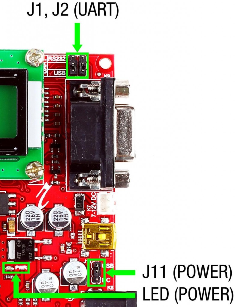
The following figures illustrate the peripheral features of the board

- J1,J2 – To select serial port/USB port for USART communication
- J11(Power jumper) – To select power source as USB/DC source
- Power LED – Glows when the board is powered
- SWITCHES – On-board switches
- LEDs – On-board SMD LEDs
- SW4 – Reset switch

- K16 – Connector for using USART in 3.3V level
- LCD – Berg strip connector for LCD
- K10 – Connector for using UART in 5V level
- K11 – Connector for interfacing servo motor
- AREF – Jumper to select AREF as 3.3V/5V
- J4,J5,J6 – Jumpers connecting LEDs to port pins PC0, PC1 & PC2
- J3 – Connects potentiometer to PA0(ADC0)
- J10 – Connects temperature sensor to PA1(ADC1)
- J7,J8,J9 – Jumpers connecting switches to port pins PD2, PD3 & PD4
- J12 – Jumper connecting buzzer to port pin PC7
- J13 – Jumper connecting RX of controller to DOUT of Zigbee
- J14 – Jumper connecting TX of controller to DIN of Zigbee
Layout![]()

How to test?![]()
- Step 1: Launch AVR Studio (click here to download )
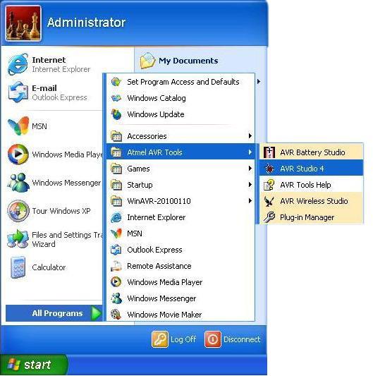
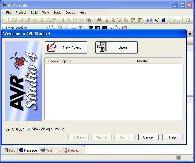
- Step 2: Click New Project to create a new project
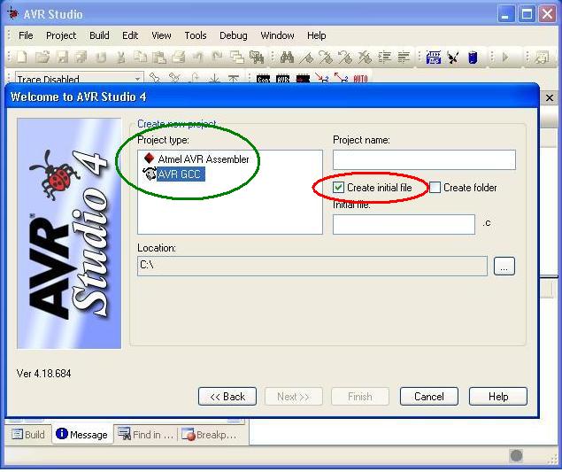
- Step 3: Under Project Type, select AVR GCC Compiler for C program(shown encircled in green).Select Create Initial file (encircled in red) option
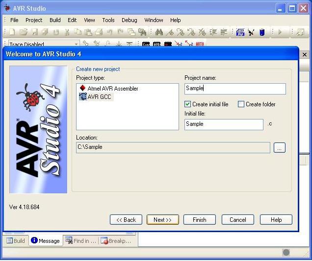
- Step 4: Give project name, file name and select location to save your project and click Next>>
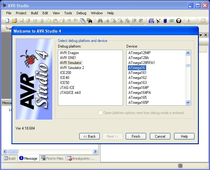
- Step 5: From the Device list, select the device (ATmega16) to be programmed and click ‘Finish‘
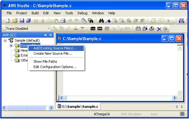
- Step 6: When the editor window opens, add the c file by right click over the Source Files >Add Existing Source Files as shown below
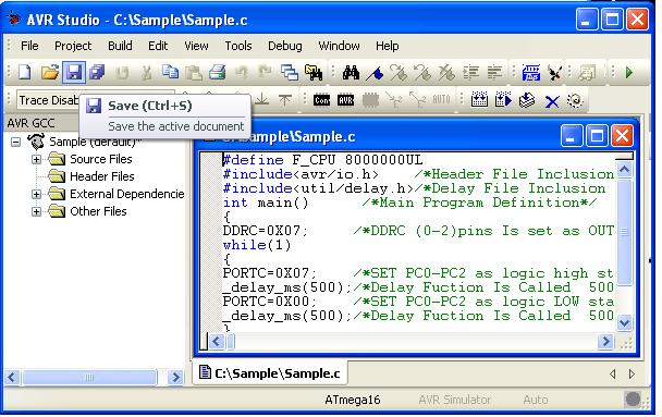
- Step 7: Enter the code and Save your file by File > Save, keyboard shortcut Ctrl + S or using Save icon
- Step 8: Build the project
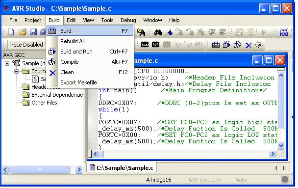 And you can view the Build window as shown below if successfully build.
Now the code can be flashed to the controller.
In the board, do the following jumper connections
- Select the power source as USB cable or DC source using jumper J11
- Select USB or serial port using jumpers J1 & J2 for flashing the code
Now power up the board. The power LED(red LED on the board) glows.
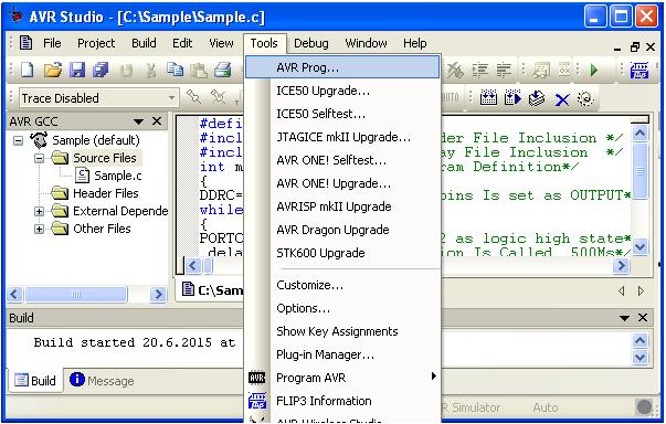
- Step 9: Select Tools > AVR Prog , simultaneously press reset switch on the mini development board
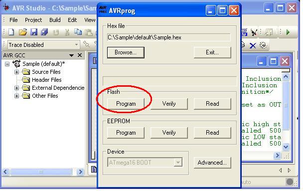
- Step 10: Select the desired hex file and click Program (encircled in red under Flash) to load the program to the device.
 After successfully flashing the code, use controller for the desired purpose.
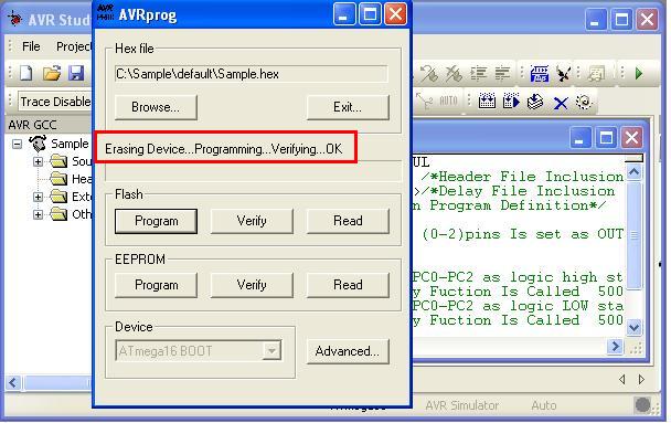
Topics related to AVR ATmega16 Mini Development Board![]()
- AVR ATmega16 Mini Development Board – Overview
- AVR ATmega16 Mini Development Board – Interfacing LED
- AVR ATmega16 Mini Development Board – Interfacing LCD
- AVR ATmega16 Mini Development Board – Serial communication(USART)
- AVR ATmega16 Mini Development Board – Interfacing Switch
- AVR ATmega16 Mini Development Board – Interfacing Buzzer
- AVR ATmega16 Mini Development Board – Interfacing POT(ADC)
- AVR ATmega16 Mini Development Board – Interfacing Temperature sensor
- AVR ATmega16 Mini Development Board – Interfacing Servo Motor
- AVR ATmega16 Mini Development Board – Interfacing μRFID
Resources![]()
How to buy?![]()
- Click here to buy rhydoLABZ AVR ATmega16 Development Board-Mini
- Click here to buy rhydoLABZ AVR ATmega32 Development Board-Mini
Support![]() Please share your ideas with us, visit our forum for discussion
Please share your ideas with us, visit our forum for discussion
Leave a Reply
You must be logged in to post a comment.