User Interface Shield
The User Interface Shield from rhydoLABZ makes it easy to use an OLED / Alphanumeric LCD with your Arduino. In addition, it has a buzzer, 3 LEDs, a variable trimmer and keypad with 5 keys with, four keys labeled for direction controls & one key labeled as select gives you a great choice to add an interactive GUI(Graphical User Interface). As user has full control over all these peripherals, this shield can easily adapt to varying requirements of user.

Features![]()
- Compatible with Arduino R3 Layout
- Operating Voltage : 5V
- Power indication LED
- 5 Momentary switches for custom menu control panel
- RST button for resetting arduino program
- Integrated preset (P1) for contrast adjustment
- Trimmer resistor (P2) for varying analog input
- On board buzzer for audio alert
- 3 LEDs in connection with GPIO pins
- Supports micro OLED display and Alphanumeric LCD
- 4-bit mode interfacing for LCD
- Plug and play with any Arduino
Hardware overview![]()


1. Buzzer
- Short J9
- Configure digital pin 2 (D2) as output
- Make D2 HIGH to turn on the buzzer
2. LEDs
UI shield comes with 4 on-board LEDs. One of them is power indicator and 3 of them are program controlled
- PWR (Red) – Turns ON once the shield is powered
- LED1, LED2, LED3 (Green) – Program controlled via pins A2, A3 and A4 respectively
To use these LEDs except power LED,
- Short J8, J7 and J6 respectively
- Configure A2 (D16), A3 (D17) and A4 (D18) as output
- Make the port pin HIGH to turn ON the corresponding LED
3. Switches
You can see 6 switches on the board
- RESET – To reset Arduino
- SW1 – SW5 (marked as LEFT, DOWN, SELECT, UP, RIGHT) – Connected to port pins via jumpers J5 – J1 in order
To use the switches,
- Short jumpers J5 – J1
- Configure D7 – D3 as input
- The port pin reads LOW if the switch is pressed
4. POTs
- LCD CONTRAST (P1) – Dedicated for LCD contrast control. Comes into action only if LCD is used
- ADC (P2) – Connected to A0 via jumper J12
5. Display
The shield supports LCD and OLED. But you can use one at a time,either OLED or LCD.
 OLED
OLED
The shield is designed for SPI interface only, so you should go with SPI configured OLED module. The jumpers for D/C (J10) and CS (J11) on the shield must be arrange its on position. Once you have set shield ready to display, upload some code and get the display printing. We used the Adafruit OLED library. you can download the example code that we used for our UI Shield. Download the library, and copy it to your libraries folder in Arduino.

The pins used for OLED interfacing are :
D/C → D8
CS → D9
RESET → D10
SCK → D13
SDA → D11
LCD
To use alphanumeric LCD with UI shield, you can directly use Arduino library for liquid crystal in four bit mode from Arduino example codes.
The pins used are :
RS → D8
E → D9
D4-D7 → D10 – D13
Note : Change library initialization as follows
|
1 |
LiquidCrystal lcd(8, 9, 13, 12, 11, 10); |
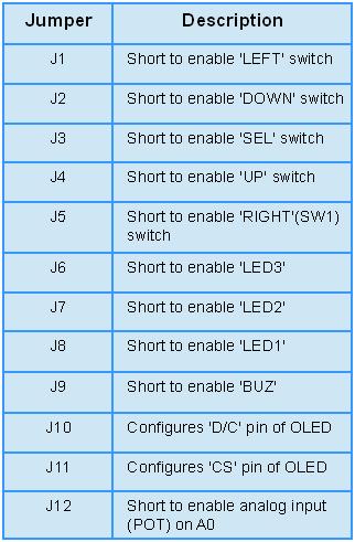
Jumper Description
Each of the modules gets enabled only by using jumpers as described in the table below. Removing the jumper frees the corresponding PORT pin. As an example, if you don’t want buzzer in your project, remove J9. This frees digital pin 2 of Arduino.
Dimension![]()

Reference![]()
Shop with us![]()
Leave a Reply
You must be logged in to post a comment.