Robot Controller Mini-Hookup Guide
The robot controller is built around the popular chip ATMega 328P running at 16MHz clock controls upto 9 servos and 2 motors. Also has motion tracker (MPU 6050) and magnetometer (HMC 5883). The motor driver used is TB6612FNG. Both wired (through FTDI connector) and wireless (via Xbee port) communication.

Connector Description
K1 : 6-pin ISP Connector
To bootload the MCU or to program the MCU directly without bootloader. 1st pin is indicated by a white dot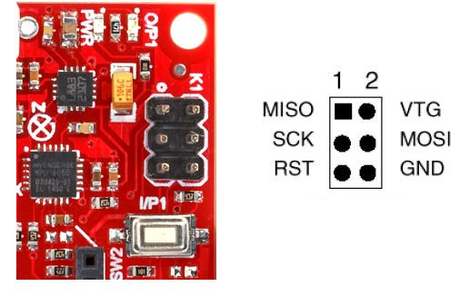
K2 : FTDI connector for communication
6 pin connector with DTR, TXD, RXD, +5V, NC, GND. Can be used for communication as well as serial programming of MCU

K3 : Supply input for board
2 pin RMC connector for powering the board. Reverse polarity protection with 5V and 3.3V regulators. Recommend supply voltage range is 7-12V DC. The terminals are labelled clearly on the rear side of the board as shown in the below image.
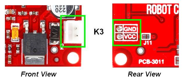
NOTE : Ensure that the power source is capable of providing enough current that is capable of driving the load
K4 : 6 pin connector with PD7(digital 7), GND, PD6(digital 6), PD3(digital 3), PD5(digital 5), PD4(digital 4)
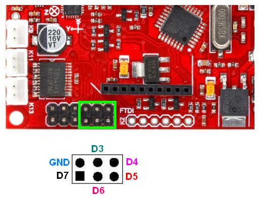
K7 : Servo Vcc
2-pin berg strip connector used to supply working voltage for servo. Goes directly without regulator. So the supply voltage should be within the working voltage range of servo. The berg strips are of different colours for easy identification and in addition, they are also labelled.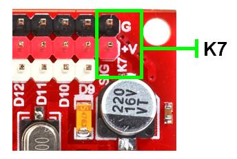
K9 : Motor Vcc, K11, K13 : Motor O/P
These 3 connectors are directly connected to motor driver IC and have their role in driving motors. All of them are labelled.
K9 is 2-pin RMC connector that provide working voltage for DC Motors. Recommended range as per datasheet is 2.5 – 13.5 V DC and maximum voltage is +15V. The terminals are labelled on the rear side of the board.
K11 and K13 are 2-pin RMC connectors that drive the motors. The 2 terminals of the motor can be tied directly to these connectors.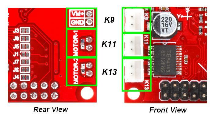
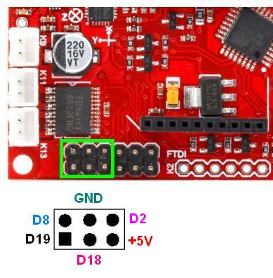
K15 : PC5 (digital 19-SCL), PB0 (digital 8), PC4 (digital 18-SDA), GND, +5, PD2 (digital 2)
 Servo
Servo
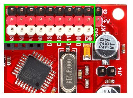
The robot controller enables you to control upto 9 servo motors. Labelled multi-colour male berg strip connectors enable you to plugin the servos with ease. Here the signal pins are directly connected to the port pins of MCU. The pin which controls each servo is labelled on the front side of the board. The SERVO LIBRARY of Arduino can be used to drive the servo motors.
> The White strips are the signal pins
>The Red strips are the Vcc pins
>The Black strips are the Gnd pins
Switches
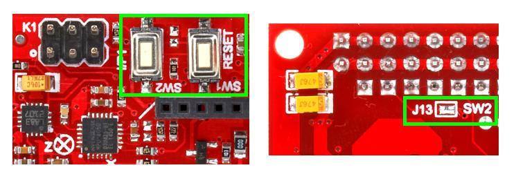
Switch is most commonly used as input device that initiates an action. There are 2 push button switches on the board
- SW1 : Arduino Reset Switch. Press this switch to Reset Arduino. This is labelled as RESET
- SW2 : User programmable switch that is connected to PB2 (digital 10) via J13
Buzzer & LEDs
Buzzer and LEDs are the most commonly used indicators. The robot controller has the following LEDs and optional buzzer interface.
PWR : Power Indicator. Turns ON when the board is powered
O/P1 : Indicator LED that is connected to PB3 (digital 11) via on-board solder jumper J12

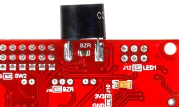
Buzzer is connected to PB5 (digital13) via on-board solder jumper J16 and transistor.
Zigbee
As mentioned above, wireless communication is made possible through Xbee port. On-board 3.3V regulator powers the Xbee and level converter circuitry enables to directly plugin the module without any additional hardware.The orientation of Xbee has been marked for ease of use.

Jumper Description
- J1 – Connects STBY to PB0 (digital 8) of MCU
- J2 – Connects SDA to PC4 (A4) of MCU
- J3 – Connects PWMA to PD2 (digital 2) of MCU
- J4 – Connects PWMB to PD3 (digital 3) of MCU
- J5 – Connects AIN1 to PD4 (digital 4) of MCU
- J6 – Connects SCL to PC5 (A5) of MCU
- J7 – Connects BIN1 to PD5 (digital 5)
- J8 – Connects AIN2 to PD6 (digital 6) of MCU
- J9 – Connects BIN2 to PD7 (digital 7) of MCU
- J10 – Selects AD0 (I2C slave address LSB) of MPU6050 as 3V3 / GND
- J11 – On-board PCB solder jumper. If populated, diode gets bypassed
- J12 – Connects O/P1 LED to PB3 (digital 11)
- J13 – Connects SW2 to PB2 (digital 10)
- J14 – If shorted, Servo Vcc becomes input supply for board also. No need to power the board separately
- J15 – Connects input voltage to PC5 (A5). Input voltage can be monitored by reading A5.
- J16 – If shorted, enables you to control buzzer with PB5 (digital13) of Arduino.
MPU6050
The MPU-60X0 is an integrated 6 DOF (Degrees of Freedom) or 6-axis MotionTracking IMU(Inertial measurement unit) sensor that combines a 3-axis gyroscope, 3-axis accelerometer, and a Digital Motion Processor (DMP) all in a small 4x4x0.9mm package. It gives six values as output – Three values from the accelerometer and three from the gyroscope
The MPU-60X0 features three 16-bit analog-to-digital converters (ADCs) for digitizing the gyroscope outputs and three 16-bit ADCs for digitizing the accelerometer outputs. For precision tracking of both fast and slow motions, the parts feature a user-programmable gyroscope full-scale range of ±250, ±500, ±1000, and ±2000°/sec (dps) and a user-programmable accelerometer full-scale range of ±2g, ±4g, ±8g, and ±16g.
The raw values read from the sensor might seem unstable because the default sensitivity is high, and the sensor returns 16 bits, but the actual valid number of bits is less than 16 bits. Since they are 16 bits, a variation of 50 is just a very small variation.
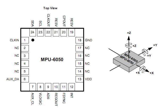
Communication with all registers of the device is performed using I2C with maximum speed of 400kHz. The slave address of the MPU-60X0 is b110100X which is 7 bits long. The LSB bit of the 7 bit address is determined by the logic level on pin AD0. If the pin is HIGH, then the address is b1101001 (69H) and the address is b1101000 (68H) if it is LOW
The following images illustrate the pinout ot the module and orientation of axes and polarity of rotation.
HMC5883
The Honeywell HMC5883L is a surface-mount, multi-chip module designed for low-field magnetic sensing with a digital interface for applications such as low-cost compassing and magnetometry. The sensor is sensitive to the earths magnetic fields in three axes – X, Y, and Z. An output is provided for each of these axes that describes the position of these axes relative to the earth’s magnetic field.
The HMC5883L sensor is a 3-axis digital magnetometer IC designed for low-field magnetic sensing. The sensor has a full-scale range of +8 to -8 Gauss and a resolution of up to 5 milli-Gauss. Communication with the HMC5883L is simple and all done through an I2C interface.
Because this is a magnetic compass if you put it near to battery, motors, metallic surface or magnetic field, the result will diverge from the actual. Also make sure to use it on a flat surface!
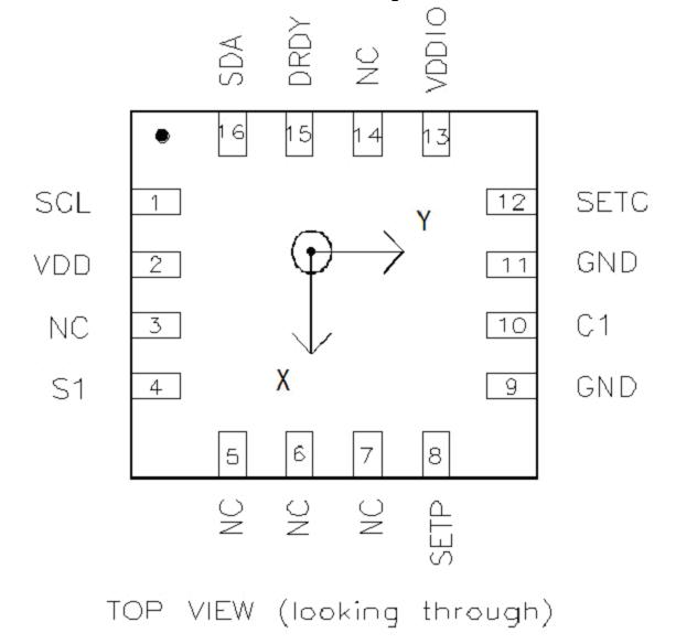
Arrow indicates direction of magnetic field that generates a positive output reading in Normal Measurement configuration.
- Spin the device around z-axis, x & y change
- Spin the device around y-axis, x & z change
- Spin the device around x-axis, y & z change
- If you hold the module so that it is parallel with the ground then it will point you in the direction of North
This device communicates with I2C protocol standard and fast modes, 100kHz and 400kHz, respectively, but does not support the high speed mode.
Arduino Libraries
The Arduino libraries necessary to obtain the accelerometer / gyro / magnetometer data and handle the calculations are available from Github. To work with MPU6050 and HMC5883, you need to have the folders “I2Cdev”, “MPU6050” and “HMC5883L” in your Arduino libraries folder
Motor Controller TB6612FNG
TB6612FNG is a driver IC for DC motor with output transistor in LD MOS structure with low ON-resistor. The driver can be used to control 2 DC motors. Two input signals, IN1 and IN2, can choose one of the four modes such as CW, CCW, short brake, and stop mode. TB6612FNG has a supply range of 2.5V to 13.5V and is capable of 1.2A continuous current and 3.2A peak current (per channel), so it works pretty well with most of the DC motors.
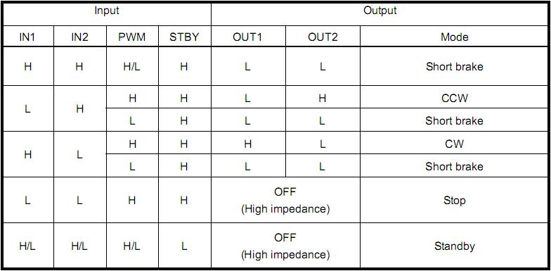
STBY : PB0 (digital 8) via J1
PWMA : PD2 (digital 2) via J3
PWMB : PD3 (digital 3) via J4
AIN1 : PD4 (digital 4) via J5
BIN1 : PD5 (digital 5) via J7
AIN2 : PD6 (digital 6) via J8
BIN2 : PD7 (digital 7) via J9
O/P -> K11 & K13
Motor Power -> K9 (recommended range as per datasheet is 2.5 V to 13.5 V)
Power up the board
Power the board with 7-12V DC through K3.
If you are providing Servo Vcc, then you can place jumper J14 in position so that the board gets powered up from the Servo Vcc. This frees up K3.
The working voltage for DC motor should be provided via K9.
Populating the on-board PCB solder jumper J11 bypasses the reverse polarity protection diode.
When the board is powered, the power indication LED lits up.
Communicating with the Robot Controller
You can communicate with Robot Controller in 2 ways
- Via 6-pin FTDI connector using a USB – TTL converter / RS232 – TTL converter
(Diagram)
- Wireless communication using Xbee. The 20-pin standard Xbee connector along with on-board 3.3V regulator and level conversion circuitry enables you to directly plug-in wireless devices with Xbee form factor without any additional hardware.
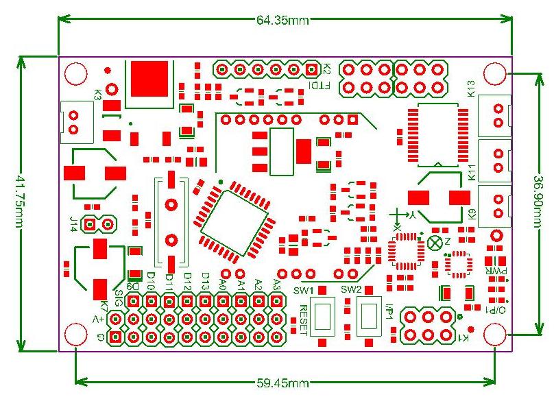
Dimension
Resources
- Datasheet – MPU6050
- Datasheet – HMC5883
- Datasheet – TB6612 FNG
- Arduino library for MPU6050 and HMC5833
- ATmega 328P pin mapping
Shop With Us

Leave a Reply
You must be logged in to post a comment.