Interfacing Gsm/Gprs/Gnss/Bluetooth Hat With Raspberry Pi 3
As in our previous posts, we make a clear picture about interfacing the GPS, GSM/GPRS modules with Raspberry pi individually. So now its time to integrate these clustered functions in to a single device suited for Raspberry pi. A new module has been introduced with these appended functionalities and it is named as per its properties, Gsm/Gprs/Gnss/Bluetooth Hat.
Communication system has been attained at its prime level by introducing this module as it prompts the IoT applications along with the location access. All the upcoming electronic systems will be accomplished with this communication schemes. The module will be highlighted when it is being interfaced with a Raspberry pi, as it can easily derive its functionalities. Eventually we can build our own mobile or tablet devices by the integration of these modules or can even up to more.
Here we brought the knowledge of basic interfacing between a Raspberry Pi3 and the HAT module. As in the HAT module, there are two ways for making the connections.
- USB interfacing
- GPIO interfacing
Here we make use of a micro USB cable for connecting Raspberry Pi with the HAT module that in-turn provides the suitable power and establish a serial communication. 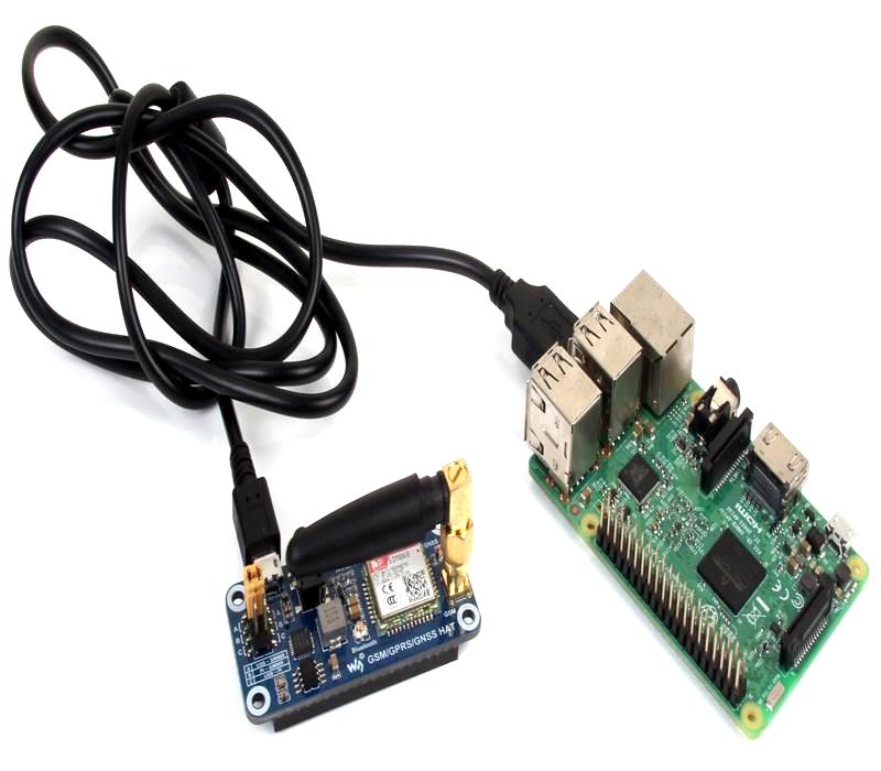
SIM 868 module is being used in this device which is a complete Quad-Band GSM/GPRS module which combines GNSS technology for satellite navigation. In the left side of the module you can see a yellow jumper connected to the suitable pins. There are four pairs of pins in which the jumpers must be shorted to make three terminal pairs (A,B,C).
A: control the SIM868 through USB TO UART
B: control the SIM868 through Raspberry Pi
C: access Raspberry Pi through USB TO UART
Here we make use of A terminal, ie the jumpers must be connected vertically in the first two pins as shown in the figure given below. 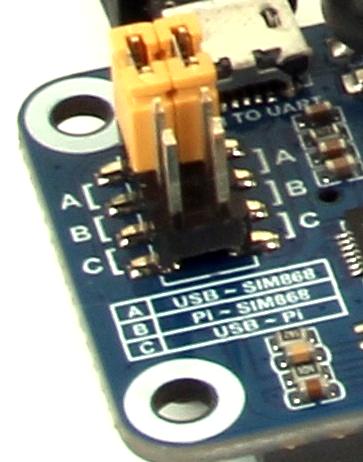
Working
- Power on the raspberry pi module with raspbian OS installed on it. Connect the hat module to the raspberry pi through USB as shown in the first figure.
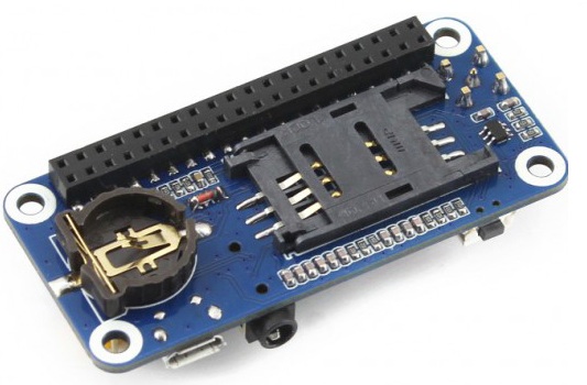
- Insert a sim card to the HAT module to perform GSM operations.
- After connecting the USB, the pwr led will be in an on state. Press the PWRKEY for 3 seconds and remove it. The STA LED (status) will also be ina an on state.
- The NET led will blink in a continuous manner and the after obtaining the range for sim card, the blinking rate will be reduced.
Programming
Here we are giving two programs in python for sending messages and for getting the GPS data on Raspberry Pi.
Code for sending messages using Gsm/Gprs/Gnss/Bluetooth Hat
|
1 2 3 4 5 6 7 8 9 10 11 12 13 14 15 16 17 18 19 20 21 22 23 24 25 26 27 28 29 30 31 32 33 34 35 36 37 38 39 40 41 42 43 44 45 46 |
import serial import RPi.GPIO as GPIO import os, time from random import randrange GPIO.setmode(GPIO.BOARD) # Enable Serial Communication port = serial.Serial("/dev/ttyUSB0", baudrate=115200, timeout=1) # Transmitting AT Commands to the Modem # '\r\n' indicates the Enter key port.write('AT'+'\r\n') rcv = port.read(10) print rcv time.sleep(.1) port.write('ATE0'+'\r\n') # Disable the Echo rcv = port.read(10) print rcv time.sleep(.1) port.write('AT+CMGF=1'+'\r\n') # Select Message format as Text mode rcv = port.read(10) print rcv time.sleep(.1) port.write('AT+CNMI=2,1,0,0,0'+'\r\n') # New SMS Message Indications rcv = port.read(10) print rcv time.sleep(.1) # Sending a message to a particular Number port.write('AT+CMGS="Mob. No."'+'\r\n') rcv = port.read(10) print rcv time.sleep(.1) port.write('Hello'+'\r\n') # Message rcv = port.read(10) print rcv port.write("\x1A") # Enable to send SMS for i in range(10): rcv = port.read(10) print rcv |
Code for getting GPS data using Gsm/Gprs/Gnss/Bluetooth Hat
Before running the code for GPS a GNSS antenna connector must be connected to the Hat module. Connect a GPS antenna to that connector and place the antenna projected to clear sky for GPS initialization.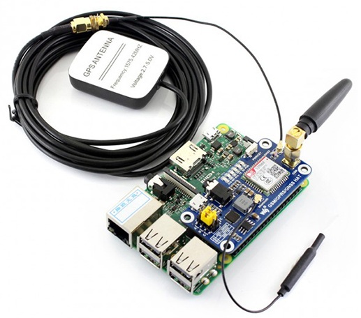 As shown in the figure above make the connections, and run the program given below in python.
|
1 2 3 4 5 6 7 8 9 10 11 12 13 14 15 16 17 18 19 20 21 22 23 24 25 26 27 28 29 30 31 32 33 34 35 36 37 38 39 40 41 42 43 44 45 46 47 48 49 50 51 52 53 54 55 56 57 58 59 60 61 62 63 64 65 66 67 68 69 70 71 72 73 74 |
#!/usr/bin/python import serial import time from decimal import * from subprocess import call def find(str, ch): for i, ltr in enumerate(str): if ltr == ch: yield i # Enable Serial Communication port = serial.Serial("/dev/ttyUSB0", baudrate=115200, timeout=1) # Transmitting AT Commands to the Modem # '\r\n' indicates the Enter key port.write('AT'+'\r\n') rcv = port.read(100) print rcv time.sleep(.1) port.write('AT+CGNSPWR=1'+'\r\n') # to power the GPS rcv = port.read(100) print rcv time.sleep(.1) port.write('AT+CGNSIPR=115200'+'\r\n') # Set the baud rate of GPS rcv = port.read(100) print rcv time.sleep(.1) port.write('AT+CGNSTST=1'+'\r\n') # Send data received to UART rcv = port.read(100) print rcv time.sleep(.1) port.write('AT+CGNSINF'+'\r\n') # Print the GPS information rcv = port.read(200) print rcv time.sleep(.1) ck=1 while ck==1: fd = port.read(200) # Read the GPS data from UART #print fd time.sleep(.5) if '$GNRMC' in fd: # To Extract Lattitude and ps=fd.find('$GNRMC') # Longitude dif=len(fd)-ps if dif > 50: data=fd[ps:(ps+50)] print data ds=data.find('A') # Check GPS is valid if ds > 0 and ds < 20: p=list(find(data, ",")) lat=data[(p[2]+1):p[3]] lon=data[(p[4]+1):p[5]] # GPS data calculation s1=lat[2:len(lat)] s1=Decimal(s1) s1=s1/60 s11=int(lat[0:2]) s1 = s11+s1 s2=lon[3:len(lon)] s2=Decimal(s2) s2=s2/60 s22=int(lon[0:3]) s2 = s22+s2 print s1 print s2 |
Python Shell Results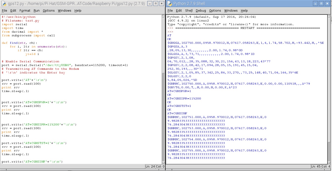
Note: To obtain an internet connection through this hat module, Please refer the link given below;
https://wiki.rhydolabz.com/?p=16325.(Use /dev/ttyUSB0 for serial communication).
Shop With US:
- Click here to buy Gsm/Gprs/Gnss/Bluetooth Hat For Raspberry Pi from rhydoLABZ.
- Click here to buy Raspberry Pi 3 Starter Kit from rhydoLABZ.
Leave a Reply
You must be logged in to post a comment.