Introduction to XBee Explorer Dongle
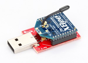
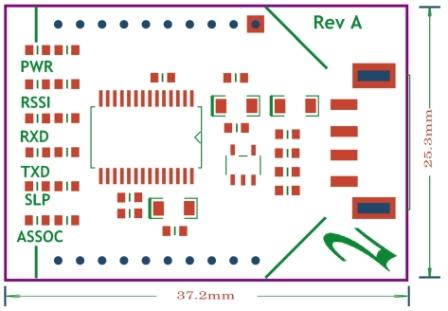
This is rhydoLABZ make XBee Explorer board with USB A Type connector for the XBee line of products which can be used as Dongle – can avoid USB cable and LAPTOP friendly!! . The board is populated with high current LDO to support most of XBee modules including XBee Pro! .The XBee Explorer Dongle will help you to reduce lot of hassles normally facing to implement Xbee Network.We have also added two more LED’s (SLEEP & Associate) apart from normal 4 LED. This help you to use latest versions XBee Modules as well. The module is self powered from USB Port itself, thanks to low dropout regulator.

After Power up the explorer Dongle board will create a virtual COM port in PC , and you can communicate with the module same as serial port devices. The Explorer board is built with FT232RL Chip from FTDI and drivers are available for Windows ,Linux and MAC.
This unit works with all XBee modules including the Series 1 and Series 2.5, standard and Pro version. Plug the Xbee Module into the XBee Explorer Dongle , attach to the LAPTOP, and you will have direct access to the serial and programming pins on the XBee unit.
Features:
- USB A Type Connector
- Built in SMD fuse for protecting PC USB Port
- Powered from PC USB Port
- High Current (500ma) 3V3 Voltage Regulator for XBee/XBee PRO Module
- 5 Onboard Status LEDs (Associate,Sleep,Tx,Rx and RSSI)
- Onboard Power LED
- High qualty PTH PCB and made by Automatic Pick and Place Machine


- When XBee Explorer Dongle is connected with USB port of PC,the PWR (blue) LED will glow on the top of module ,it shows power indication.
- For a quick installation on XBee Explorer Dongle and connection details please read the blog…
- Here we are using a paired Zigbee, to construct a simple point-to-point network.One of the devices must be a Coordinator and the other must be a Router (an ‘endpoint’ device).
- After completion of installation setup SLP LED(Green) is turn ON and also ASSOC LED(Red) will blink rapidly 2 times per seconds(Association Confirmation received to the endpoint device from the Coordinator) or ASSOC LED will not blink if the End Device has not associated.
- During the transmission TXD led blinks as per the data rate and at the time of reception RXD led blinks.
- RSSI LED(yellow) on top of the board is connected to the RSSI (Received Signal Strength Indicator) pin of the XBee module. XBee outputs a PWM signal on this pin which is directly proportional to the quality of the RF signal, until the last packet was received by it. This PWM signal applied to the RSSI LED will vary its brightness as per the quality of the RF signal,better the RF signal brighter the LED.
- Placing XBee module on XBee Explorer Dongle is shown below.
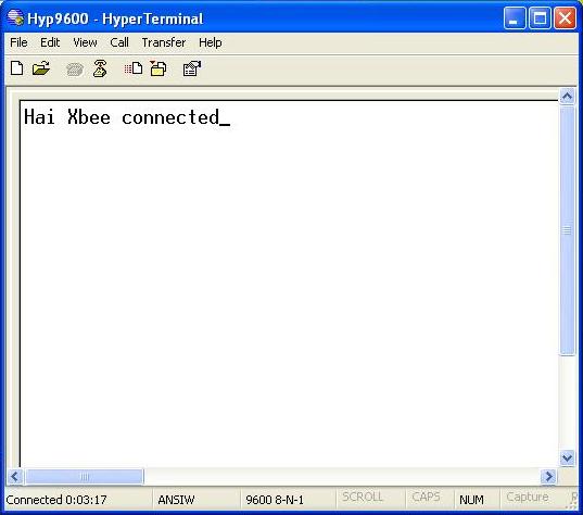
- In this example we are making communication between two paired zigbee COM PORT of coordinator zigbee is set in Hyperterminal and wrote a message like here it is “Hai Xbee connected” sent it to end point Xbee.
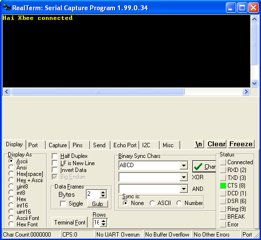
- And we opened other terminal window i.e realterm and COM PORT set in realterm terminal window is of End point Xbee and received message sent from coordinator Xbee in realterm.Click here to download realterm.

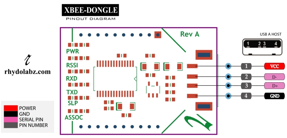
Schematic
Realterm Software.
How to Buy:


Q.Which XBee modules are compatible with XBee Explorer Dongle ?
Ans.This XBee Explorer Dongle works with all XBee modules including Series 1 and Series 2.5, standard and Pro version.
Q.How to connect XBee Explorer Dongle with PC?
Ans.When XBee Explorer Dongle is connected via USB port of PC,the PWR (blue) LED will glow on the top of module,after that please go through the link XBee Explorer Dongle for installation procedure.

Leave a Reply
You must be logged in to post a comment.