ARM LPC2129 Mini Development Board – LCD Interfacing
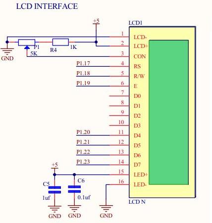
Here ARM LPC2129 Mini Development Board is interfaced with a LCD module (2×16) operating at 5V. The voltage at the third pin of the LCD used to adjusting contrast. LCD can work either in 4 or 8 bit mode. Here, the circuit is designed to work in 4bit mode. Control lines (RS, R/W ,E) are connected to port pins P1.17 ,P1.18 , P1.19 and data lines (D4-D7) to port pins P1.20 ,P1.21 ,P1.22 ,P1.23 in 4bit mode. For reliable Performance, LCD has to be initialized. On powering microcontroller send initialization commands to LCD for better working. The sample code below gives LCD display output ” RhydoLABZ ” in line 1 and “Cochin” in line 2 . Schematic:
![]()
 Sample code :
![]()
|
1 2 3 4 5 6 7 8 9 10 11 12 13 14 15 16 17 18 19 20 21 22 23 24 25 26 27 28 29 30 31 32 33 34 35 36 37 38 39 40 41 42 43 44 45 46 47 48 49 50 51 52 53 54 55 56 57 58 59 60 61 62 63 64 65 66 67 68 69 70 71 72 73 74 75 76 77 78 79 80 81 82 83 84 85 86 87 88 89 90 91 92 93 94 95 96 97 98 99 100 101 102 103 104 105 106 107 108 109 110 111 112 113 114 115 116 117 118 119 120 121 122 123 124 125 126 127 128 129 130 131 132 133 134 135 136 137 138 139 140 141 142 143 144 145 146 147 148 149 150 151 152 153 154 155 156 157 158 159 160 161 162 163 164 165 166 167 168 169 170 171 172 173 174 175 176 177 178 179 180 |
/******************************************************************************************************* * LCD PROGRAM * ******************************************************************************************************** * HEADER DECLARATIONS * *******************************************************************************************************/ #include<lpc21xx.h> #define RS 0x00020000 /* 17th pin RS */ #define RW 0X00040000 /* 18th pin R/W */ #define EN 0X00080000 /* 19th pin EN */ #define CLR 0X00FE0000 /******************************************************************************************************* * Function : Delay * * Description : command for Delay * * Parameter : x, the value for delay *******************************************************************************************************/ int Delay(unsigned int x) { x=x*12000; while(x!=0){ x--; } return 0; } /******************************************************************************************************* * Function : Lcd_Command * * Description : command for lcd * * Parameter : command, address value ********************************************************************************************************/ void Lcd_Command(char command) { int Temp; IO1CLR = CLR; /* Clear ALL 16-23 Pins */ IO1SET = EN; /* SET 19th Pin [EN] */ IO1CLR = RS; /* Clear 17th Pin [RS] */ IO1CLR = RW; /* Clear 18th Pin [R/W] */ Temp = (command & 0xF0) << 16; /* Higher Nibble Extracting 0X30 [3-High] & [4-7] Shifted To [20-23] */ IO1SET = IO1SET | Temp; /* 0X00080000 | 0X00300000[Shifted] = 0X00380000 [Only '3' Is in [20-23]pins */ Delay(2); /* Minimum Delay Time */ IO1CLR = EN; /* ENABLE High-Low Transition */ } /******************************************************************************************************** * Function : Lcd_Command1 * * Description : command for lcd * * Parameter : command1, address value ********************************************************************************************************/ void Lcd_Command1(char command1) { int Temp; IO1CLR = CLR; /* Clear ALL 16-23 Pins */ IO1SET = EN; /* SET 19th Pin [EN] */ IO1CLR = RS; /* Clear 17th Pin [RS] */ IO1CLR = RW; /* Clear 18th Pin [R/W] */ Temp = (command1 & 0xF0) << 16; /* Higher Nibble Extracting 0X30 [3-High] & [4-7] Shifted To [20-23] */ IO1SET = IO1SET | Temp; /* 0X00080000 | 0X00300000[Shifted] = 0X00380000 [Only '3' Is in [20-23]pins */ Delay(2); /* Minimum DelayTime */ IO1CLR = EN; /* ENABLE High-Low Transition */ IO1CLR = CLR; /* Clear ALL 16-23 Pins */ IO1SET = EN; /* SET 19th Pin [EN] */ IO1CLR = RW; /* Clear 17th Pin [RS] */ IO1CLR = RS; /* Clear 18th Pin [R/W] */ Temp = (command1 & 0x0F) << 20; /* Lower Nibble [0-3] Shifted To [20-23] & [0-3] Shifted To [20-23] */ IO1SET = IO1SET | Temp; /* 0X00080000 | 0X00800000[Shifted] = 0X00880000 [Only '8' Is in [20-23]pins */ Delay(2); /* Minimum Delay Time */ IO1CLR = EN; /* ENABLE High-Low Transition */ } /******************************************************************************************************* * Function : Lcd_Data * * Description : display command for lcd * * Parameter : data, single data *******************************************************************************************************/ void Lcd_Data(char data) { int Temp; IO1CLR = CLR; /* Clear ALL 16-23 Pins */ IO1SET = EN; /* SET 19th Pin [EN] */ IO1CLR = RW; /* Clear 18th Pin [R/W] */ IO1SET = RS; /* Clear 17th Pin [RS] */ Temp = (data & 0xF0) << 16; /* Higher Nibble Extracting 0X30 [3-High] & [4-7] Shifted To [20-23] */ IO1SET = IO1SET | Temp; /* 0X00080000 | 0X00300000[Shifted] = 0X00380000 [Only '3' Is in [20-23]pins */ Delay(2); /* Minimum DelayTime */ IO1CLR = EN; /* ENABLE High-Low Transition */ IO1CLR = CLR; /* Clear ALL 16-23 Pins */ IO1SET = EN; /* SET 19th Pin [EN] */ IO1CLR = RW; /* Clear 18th Pin [R/W] */ IO1SET = RS; /* Clear 17th Pin [RS] */ Temp = (data & 0x0F)<<20; /* Lower Nibble [0-3] Shifted To [20-23] & [0-3] Shifted To [20-23] */ IO1SET = IO1SET | Temp; /* 0X00080000 | 0X00800000[Shifted] = 0X00880000 [Only '8' Is in [20-23]pins */ Delay(2); /* Minimum DelayTime */ IO1CLR = EN; /* ENABLE High-Low Transition */ } /******************************************************************************************************* * Function : lCD_string * * Description : display group of data * * Parameter : dat, group of data *******************************************************************************************************/ void Lcd_String(unsigned char *dat) { while(*dat!='\0') { Lcd_Data(*dat); dat++; } } /****************************************************************************************************** * Function : Lcd_Init * * Description : Funtion for initialize LCD to display data * * Parameter : None ********************************************************************************************************/ void Lcd_Init(void) { Delay(15); /* Delay (1.5ms) */ Lcd_Command(0x30); /* Single line enable(2X16) */ Delay(10); /* Delay (10us) */ Lcd_Command(0x30); /* Single line enable(2X16) */ Delay(5); /* Delay (0.5ms) */ Lcd_Command(0x30); /* Single line enable(2X16) */ Lcd_Command(0x20); /* 4-bit Mode Enable */ Lcd_Command1(0x28); /* Double line enable (2X16) */ Lcd_Command1(0x01); /* Clear LCD */ Lcd_Command1(0x06); /* Automatic increment */ Lcd_Command1(0x0C); /* Cursor OFF /Display ON */ } /******************************************************************************************************** * Function : PORT INITIALIZATION * * Description : Funtion for initialize ports * * Parameter : None ********************************************************************************************************/ void Port_Initial(void) { IO1DIR = 0x00FE0000; /* 17-23 Pins As Output for LCD */ IO0DIR = 0x00000000; PINSEL0 = 0x00000000; PINSEL1 = 0x05000000; PINSEL2 = 0x00000000; } /******************************************************************************************************** * CODE AREA * ********************************************************************************************************/ int main() { Port_Initial(); /* Initialize direction & pinsel of ports */ Lcd_Init(); /* LCD initialization */ Lcd_String(" RhydoLABZ "); /* LCD display */ Lcd_Command1(0xC0); /* LCD Location (0xC0) */ Lcd_String(" Cochin "); /* LCD display */ while(1); } /********************************************END********************************************************/ |
OUTPUT![]()

Topics related to ARM LPC2129 Mini Development Board![]()
- ARM LPC2129 Mini Development Board – Overview
- ARM LPC2129 Mini Development Board – LED Interfacing
- ARM LPC2129 Mini Development Board – LCD Interfacing
- ARM LPC2129 Mini Development Board – UART0 Interfacing
- ARM LPC2129 Mini Development Board – UART1 Interfacing
- ARM LPC2129 Mini Development Board – Switches Interfacing
- ARM LPC2129 Mini Development Board – BUZZER Interfacing
- ARM LPC2129 Mini Development Board – POT Interfacing (ADC)
- ARM LPC2129 Mini Development Board – Temperature Sensor Interfacing(ADC)
- ARM LPC2129 Mini Development Board – Interfacing Servo motor
- ARM LPC2129 Mini Development Board – CAN Interfacing
Resources![]()
- Softwares
- Datasheets
How to buy?![]()
- Click here to buy rhydoLABZ ARM LPC2138 Mini Development Board
- Click here to buy rhydoLABZ ARM LPC2148 Mini Development Board
- Click here to buy rhydoLABZ ARM LPC2129 Mini Development Board
Support![]() Please share your ideas with us,visit our forum for discussion
Please share your ideas with us,visit our forum for discussion
Leave a Reply
You must be logged in to post a comment.