PIC18F4520 – Interfacing POT(ADC)
PIC18F4520 mini development board has a POT connected to pin RA0 i.e, channel0 via jumper J16. Sample code to check the ADC module of PIC18F4520 with potentiometer is given below. The output is displayed on LCD and the variation can be checked with the POT.

Schematic![]()
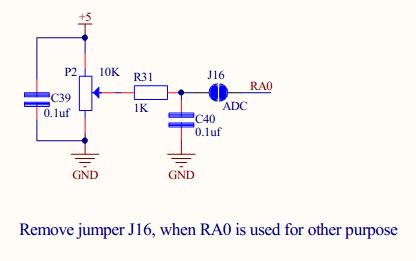 Note: To use potentiometer, don’t forget to short jumper J16. Leaving it open frees RA0 and it can be used for any other desired purpose.
Sample Code![]()
|
1 2 3 4 5 6 7 8 9 10 11 12 13 14 15 16 17 18 19 20 21 22 23 24 25 26 27 28 29 30 31 32 33 34 35 36 37 38 39 40 41 42 43 44 45 46 47 48 49 50 51 52 53 54 55 56 57 58 59 60 61 62 63 64 65 66 67 68 69 70 71 72 73 74 75 76 77 78 79 80 81 82 83 84 85 86 87 88 89 90 91 92 93 94 95 96 97 98 99 100 101 102 103 104 105 106 107 108 109 110 111 112 113 114 115 116 117 118 119 120 121 122 123 124 125 126 127 128 129 130 131 132 133 |
/************************************************************************* HEADER FILES **************************************************************************/ #include<pic18.h> /************************************************************************* FUNCTION DECLARATIONS **************************************************************************/ void Delay_us(int us); void Data(int Value); void Cmd(int Value); void Send2LCD(const char Adr, const char *Lcd); /************************************************************************* VARIABLE DECLARATIONS **************************************************************************/ int k,ADC_Value; char ADC_Array[5]; /************************************************************************* MAIN FUNCTION **************************************************************************/ void main() { TRISA = 0XFF; /* Set PORTA as input for channel 0 */ TRISC = 0X00; /* PORTC(control lines) configured as o/p*/ TRISD = 0X00; /* PORTD(data lines) configured as o/p */ Delay_us(25); Cmd(0X30); Delay_us(25); /* LCD Specification Command */ Cmd(0X30); Delay_us(25); /* LCD Specification Command */ Cmd(0X30); Delay_us(25); /* LCD Specification Command */ Cmd(0X38); /* Double Line Display Command */ Cmd(0X06); /* Auto Increment Location Address */ Cmd(0X0C); /* Display ON Command */ Cmd(0X01); /* Clear Display Command */ Delay_us(1000); Send2LCD(0x80,"ADC Result: "); ADCON0 = 0x01; /* ADON=1 and other bits configured as 0 */ ADCON1 = 0x00; /* All bits are configured as 0 in ADCON1*/ ADFM = 1; /* Result format right justified */ ACQT1 = 1; /* A/D acqusition time select is 4TAD */ ADCS1 = 1; /* A/D conversion clock is Focs/32 */ while(1) { GO = 1; /* Set A/D conversion status bit (conversion in progress) */ while(GO==1); /* Wait until A\D conversion completes */ ADC_Value = ADRESH; /* Copy the 2 bits in ADRESH to ADC_Value*/ ADC_Value = ADC_Value<<8; /* Shift it 8 bits to left */ ADC_Value = ADC_Value+ADRESL; /* Add left shifted value to ADRESL */ for(k=0; k<=3; k++) /* Convert the result into ASCII */ { /* Separate each digit of the integer */ ADC_Array[k] = ADC_Value%10+'0'; ADC_Value = ADC_Value/10; } Cmd(0X8C); for(k=3; k>=0; k--) { Data(ADC_Array[k]); /* Display the result on LCD */ } } } /************************************************************************* * Function : Cmd * * * * Description : Function to send a command to LCD * * * * Parameters : Value - command to be sent * **************************************************************************/ void Cmd(int Value) { PORTD = Value; /* Write the command to data lines */ RC0 = 0; /* RS-0(command register) */ RC1 = 1; /* E-1(enable) */ Delay_us(25); RC1 = 0; /* E-0(enable) */ } /************************************************************************* * Function : Data * * * * Description : Function to display single character on LCD * * * * Parameters : Value - character to be displayed * **************************************************************************/ void Data(int Value) { PORTD = Value; /* Write the character to data lines */ RC0 = 1; /* RS-1(data register) */ RC1 = 1; /* E-1(enable) */ Delay_us(25); RC1 = 0; /* E-0(enable) */ } /************************************************************************* * Function : Send2LCD * * * * Description : Function to display string on LCD * * * * Parameters : loc - location * * String to be displayed * **************************************************************************/ void Send2LCD(const char Adr, const char *Lcd) { Cmd(Adr); /* Address of location to display string */ while(*Lcd!='\0') /* Check for termination character */ { Data(*Lcd); /* Display the character on LCD */ Lcd++; /* Increment the pointer */ } } /************************************************************************* * Function : Delay_us * * * * Description : Function for 1 microsecond delay * * * * Parameter : us - delay in microseconds * **************************************************************************/ void Delay_us(int us) { us = us>>1; while(us!=1) us--; } /*************************** END OF PROGRAM ****************************/ |
Topics related to PIC18F4520 Mini Development Board![]()
- PIC18F4520 Mini Development Board – Overview
- PIC18F4520 Mini Development Board – Interfacing LED
- PIC18F4520 Mini Development Board – Interfacing LCD
- PIC18F4520 Mini Development Board – Serial communication(USART)
- PIC18F4520 Mini Development Board – Interfacing Switch
- PIC18F4520 Mini Development Board – Interfacing Buzzer
- PIC18F4520 Mini Development Board – Interfacing POT(ADC)
- PIC18F4520 Mini Development Board – Interfacing Temperature sensor
- PIC18F4520 Mini Development Board – Interfacing Servo Motor
- PIC18F4520 Mini Development Board – Interfacing μRFID
Resources![]()
- Datasheets
How to buy?![]()
- Click here to buy rhydoLABZ PIC 16F877A Mini Development Board
- Click here to buy rhydoLABZ PIC 18F4520 Mini Development Board
- Click here to buy rhydoLABZ PIC 18F4550 Mini Development Board
- Click here to buy rhydoLABZ PIC 18F4580 Mini Development Board
Support![]() Please share your ideas with us, visit our forum for discussion
Please share your ideas with us, visit our forum for discussion
Leave a Reply
You must be logged in to post a comment.