PIC18F4520 – Interfacing LCD
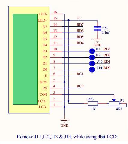
Here PIC18F4520 Mini Development Board is interfaced with a LCD module (2×16) operating at 5V. The voltage at the third pin of the LCD used to adjusting contrast. Control lines (RS, R/W ,E) are connected to port pins (RS)RC0, (E)RC1 and data lines (D0-D7) to port pins RD0-RD7 where R/W is GND. For reliable Performance, LCD has to be initialized. On powering microcontroller send initialization commands to LCD for better working. The sample code below gives LCD display output ” RhydoLABZ ” in line 1 and “Dev Board” in line 2 .
Note: In default we may work out LCD in 8bit mode (jumpers are shorted from RD0 to RD3), where as if the jumpers are left open then LCD can be operated in 4 bit mode.

Schematic![]()
Sample Code (8-bit)![]()
|
1 2 3 4 5 6 7 8 9 10 11 12 13 14 15 16 17 18 19 20 21 22 23 24 25 26 27 28 29 30 31 32 33 34 35 36 37 38 39 40 41 42 43 44 45 46 47 48 49 50 51 52 53 54 55 56 57 58 59 60 61 62 63 64 65 66 67 68 69 70 71 72 73 74 75 76 77 78 79 80 81 82 83 84 85 86 87 88 89 90 91 92 93 94 95 96 97 98 99 100 101 102 |
/************************************************************************* HEADER FILES **************************************************************************/ #include<pic18.h> /************************************************************************* FUNCTION DECLARATIONS **************************************************************************/ void Delay_us(int us); void Data(int Value); void Cmd(int Value); void Send2Lcd(const char Adr, const char *Lcd); /************************************************************************* MAIN FUNCTION **************************************************************************/ void main() { TRISC=0X00; /* PORTC(control lines) configured as o/p */ TRISD=0X00; /* PORTD(data lines) configured as o/p */ Delay_us(25); Cmd(0X30); /* LCD Specification Commands */ Delay_us(25); Cmd(0X30); /* LCD Specification Commands */ Delay_us(25); Cmd(0X30); /* LCD Specification Commands */ Delay_us(25); Cmd(0X38); /* Double Line Display Command */ Cmd(0X06); /* Auto Increment Location Address Command */ Cmd(0X0C); /* Display ON Command */ Cmd(0X01); /* Clear Display Command */ Delay_us(1000); Send2Lcd(0x84,"rhydoLABZ"); /* Displays string in the first line */ Send2LCD(0xc5,"Cochin"); /* Displays string in the second line */ while(1); } /************************************************************************* * Function : Cmd * * * * Description : Function to send a command to LCD * * * * Parameters : Value - command to be sent * **************************************************************************/ void Cmd(int Value) { PORTD = Value; /* Write the command to data lines */ RC0 = 0; /* RS-0(command register) */ RC1 = 1; /* E-1(enable) */ Delay_us(25); RC1 = 0; /* E-0(enable) */ } /************************************************************************* * Function : Data * * * * Description : Function to display single character on LCD * * * * Parameters : Value - character to be displayed * **************************************************************************/ void Data(int Value) { PORTD = Value; /* Write the character to data lines */ RC0 = 1; /* RS-1(data register) */ RC1 = 1; /* E-1(enable) */ Delay_us(25); RC1 = 0; /* E-0(enable) */ } /************************************************************************* * Function : Send2LCD * * * * Description : Function to display string on LCD * * * * Parameters : Adr - location * * String to be displayed * **************************************************************************/ void Send2Lcd(const char Adr, const char *Lcd) { Cmd(Adr); /* Address of location to display string */ while(*Lcd!='\0') /* Check for termination character */ { Data(*Lcd); /* Display the character on LCD */ Lcd++; /* Increment the pointer */ } } /************************************************************************* * Function : Delay_us * * * * Description : Function for 1 microsecond delay * * * * Parameter : us - delay in microseconds * **************************************************************************/ void Delay_us(int us) { us=us>>1; while(us!=1) us--; } /*************************** END OF PROGRAM ****************************/ |
Topics related to PIC18F4520 Mini Development Board![]()
- PIC18F4520 Mini Development Board – Overview
- PIC18F4520 Mini Development Board – Interfacing LED
- PIC18F4520 Mini Development Board – Interfacing LCD
- PIC18F4520 Mini Development Board – Serial communication(USART)
- PIC18F4520 Mini Development Board – Interfacing Switch
- PIC18F4520 Mini Development Board – Interfacing Buzzer
- PIC18F4520 Mini Development Board – Interfacing POT(ADC)
- PIC18F4520 Mini Development Board – Interfacing Temperature sensor
- PIC18F4520 Mini Development Board – Interfacing Servo Motor
- PIC18F4520 Mini Development Board – Interfacing μRFID
Resources![]()
- Datasheets
How to buy?![]()
- Click here to buy rhydoLABZ PIC 16F877A Mini Development Board
- Click here to buy rhydoLABZ PIC 18F4520 Mini Development Board
- Click here to buy rhydoLABZ PIC 18F4550 Mini Development Board
- Click here to buy rhydoLABZ PIC 18F4580 Mini Development Board
Support![]() Please share your ideas with us, visit our forum for discussion
Please share your ideas with us, visit our forum for discussion
Leave a Reply
You must be logged in to post a comment.