PIC18F4550 – Serial communication(USART)
The USART module of PIC18F4550 uses pins RC7 & RC6 for reception & transmission respectively. The mini development board can communicate with PC/external modules through
- USB port via CP2102
- Serial port via MAX232
- RMC connector K15 in 5V level
- RMC connector K17 in 3.3V level
Besides, USART is also used for interfacing Zigbee & RFID reader.
Schematic![]()


Note:
- 3V3 USART communication through K17 is possible only if the jumpers J13 and J14 (XBTX, XBRX) are shorted.
- For communicating through K15 & K17, remove jumpers J3 & J4
Sample Code![]()
The sample code to check USART module is given below. Initially the letter ‘A’ gets transmitted. Then, upon receiving a character, the same gets retransmitted.
|
1 2 3 4 5 6 7 8 9 10 11 12 13 14 15 16 17 18 19 20 21 22 23 24 25 26 27 28 29 30 |
/********************************************************************** HEADER FILE ***********************************************************************/ #include<pic18.h> /********************************************************************** MAIN FUNCTION ***********************************************************************/ void main() { TRISC7 = 1; /* RC7(RX) configured as i/p */ TRISC6 = 1; /* RC6(TX) configured as o/p */ TXSTA = 0X20; /* Transmission Enable(TXEN=1,SYNC=0,BRGH=1) */ RCSTA = 0X90; /* Rception Enable (SPEN=1,CREN=1) */ BAUDCON = 0x40; /* Baudrate control Register */ SPBRG = 0X4D; /* 9600 brgh=0 */ TXREG = 'A'; /* Load the character to be transmitted */ while(!TRMT); /* Wait here till transmission is complete */ while(1) { if(RCIF==1) /* Set when a character is received */ { RCIF=0; /* Clear Receive interrupt flag bit */ TXREG = RCREG; /* Retransmit the received character */ while(!TRMT); /* Wait here till transmission is complete */ } } } /************************ END OF PROGRAM ****************************/ |
Output![]()
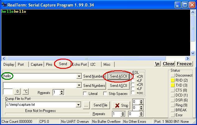
The following screenshots explain how to test the sample code using RealTerm (click to download).
- Step 1: Open RealTerm
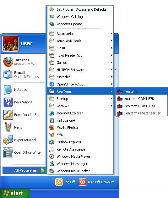
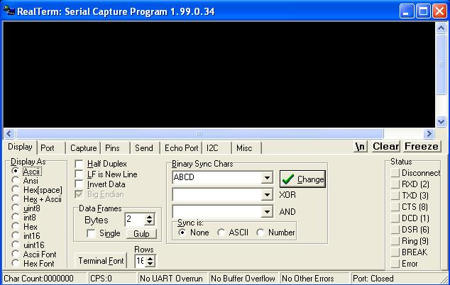
- Step 2: RealTerm opens as shown below
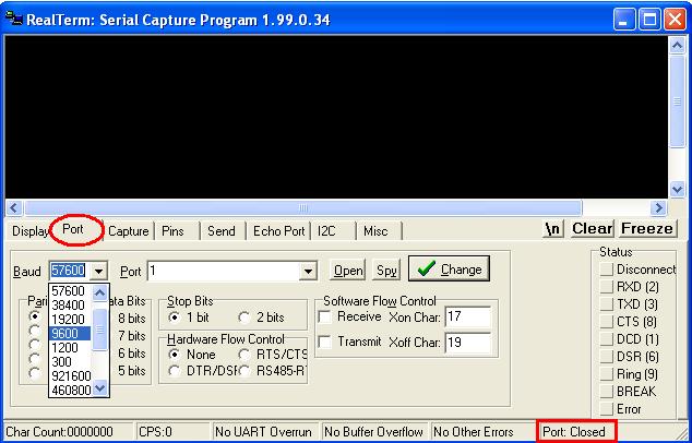
- Step 3: Go to ‘Port’ option, set correct baudrate (which is set as 9600 in the sample code) and correct port
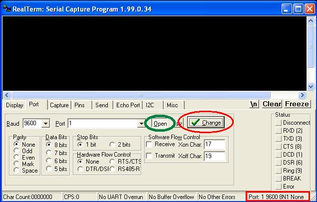
- Step 4: Click ‘Change’ (encircled in red) to apply the changes. Now check the status of Port. If it is closed, click ‘Open’ button (encircled in green) to open it.
- Step 5: To check reception, go to Send option, type the string in the space provided(encircled in green) and click Send ASCII button. The first “hello” in green colour is transmitted from PC & that in yellow colour is retransmitted by the controller
Topics related to PIC18F4550 Mini Development Board![]()
- PIC18F4550 Mini Development Board – Overview
- PIC18F4550 Mini Development Board – Interfacing LED
- PIC18F4550 Mini Development Board – Interfacing LCD
- PIC18F4550 Mini Development Board – Serial communication(USART)
- PIC18F4550 Mini Development Board – Interfacing Switch
- PIC18F4550 Mini Development Board – Interfacing Buzzer
- PIC 18F4550 Mini Development Board – Interfacing POT(ADC)
- PIC18F4550 Mini Development Board – Interfacing Temperature sensor
- PIC18F4550 Mini Development Board – Interfacing Servo Motor
- PIC18F4550 Mini Development Board – Interfacing μRFID
Resources![]()
- Datasheets
How to buy?![]()
- Click here to buy rhydoLABZ PIC 16F877A Mini Development Board
- Click here to buy rhydoLABZ PIC 18F4520 Mini Development Board
- Click here to buy rhydoLABZ PIC 18F4550 Mini Development Board
- Click here to buy rhydoLABZ PIC 18F4580 Mini Development Board
Support![]() Please share your ideas with us, visit our forum for discussion
Please share your ideas with us, visit our forum for discussion
Leave a Reply
You must be logged in to post a comment.