PIC18F4550 Mini Development Board – Overview
The PIC18F4550 Mini Development Board from rhydoLABZ can be used to evaluate and demonstrate the capabilities of Microchip PIC18F4550 microcontrollers. The board is designed for general purpose applications and includes a variety of hardwares to exercise microcontroller peripherals.Ideally suitable for training and development purposes.

Key Features:![]()
- Compact and Ready to use
- Professional EMI/RFI Complaint PCB Layout for Noise Reduction
- High Quality Two layer PTH PCB
- Board supports PIC16F877A, PIC18F4520, PIC18F4580 series
- No separate power adapter required (USB power source)
- External power supply ranges from 7V to 12V Adapter (any standard 9-12V power supply)option
- RS-232 and CP2102 Interface (for direct connection to PC’s serial port)
- On board two line LCD display(2×16)
- On board Reset button
- Built in potentiometer interface for ADC
- On board Temperature Sensor Interface
- On board Buzzer Interface
- On board JTAG connector for Debugging/Programming
- On board ICSP connector
- On board 20 MHz crystal oscillator
- On board DB9 connector and USB connector
- On board interface to CAN bus
- There is a provision for interface Zigbee
- There is a provision for interface RFID
- There is a provision for interface Servo motor
- There is provision for adding mini bread board ,if needed.
- Male and Female berg strip to access port pins
PIC18F4550 Chip Specifications![]()
- Only 35 single-word instructions to learn
- 100,000 Erase/Write Cycle Enhanced Flash Program Memory Typical
- 1,000,000 Erase/Write Cycle Data EEPROM Memory Typical
- Self-Programmable under Software Control
- Priority Levels for Interrupts
- 8 x 8 Single-Cycle Hardware Multiplier
- Extended Watchdog Timer (WDT):
- Programmable period from 41 ms to 131s
- Programmable Code Protection
- Single-Supply 5V In-Circuit Serial Programming™ (ICSP™) via Two Pins
- In-Circuit Debug (ICD) via Two Pins
- Optional Dedicated ICD/ICSP Port (44-pin, TQFP package only)
- Wide Operating Voltage Range (2.0V to 5.5V)
- High-Current Sink/Source: 25 mA/25 mA
- Three External Interrupts
- Four Timer modules (Timer0 to Timer3)
- Up to 2 Capture/Compare/PWM (CCP) modules:
- Capture is 16-bit, max. resolution 5.2 ns (TCY/16)
- Compare is 16-bit, max. resolution 83.3 ns (TCY)
- PWM output: PWM resolution is 1 to 10-bit
- Enhanced Capture/Compare/PWM (ECCP) module:
- Multiple output modes
- Selectable polarity
- Programmable dead time
- Auto-shutdown and auto-restart
- Enhanced USART module:
- LIN bus support
- Master Synchronous Serial Port (MSSP) module Supporting 3-Wire SPI (all 4 modes) and I2C™ Master and Slave modes
- 10-Bit, Up to 13-Channel Analog-to-Digital Converter (A/D) module with Programmable Acquisition Time
- Dual Analog Comparators with Input Multiplexing
- Four Crystal modes, including High-Precision PLL for USB
- Two External Clock modes, Up to 48 MHz
- Internal Oscillator Block:
- 8 user-selectable frequencies, from 31 kHz to 8 MHz
- User-tunable to compensate for frequency drift
- Secondary Oscillator using Timer1 @ 32 kHz
- Dual Oscillator Options allow Microcontroller and
- USB module to Run at Different Clock Speeds
- Fail-Safe Clock Monitor:
- Allows for safe shutdown if any clock stops
- Low Speed (1.5 Mb/s) and Full Speed (12 Mb/s)
- Supports Control, Interrupt, Isochronous and Bulk Transfers
- Supports up to 32 Endpoints (16 bidirectional)
- 1 Kbyte Dual Access RAM for USB
- On-Chip USB Transceiver with On-Chip Voltage Regulator
- Interface for Off-Chip USB Transceiver
- Streaming Parallel Port (SPP) for USB streaming transfers (40/44-pin devices only)
The following figures illustrate the peripheral features of the board:

- ICSP (K10) – Connector for programming
- SW (RESET) – Reset switch
- Power LED – Glows when the board is powered
- LED – 3 x On-board SMD LED s
- SWITCH – 3 x On-board switches
- J18(Power jumper) – To select power source as USB/DC source
- J3,J4 – To select programming source as serial port/USB port

- K15 – Connector for accessing UART 5V
- K14 – Connector for accessing CAN
- K16 – Connector for interfacing Servo Motor at RE1
- J16 – Connects Potentiometer to RA0
- J17 – Connects Temperature Sensor to RA1
- J1,J2,J10 – Jumpers connects LEDs to port pins RB1, RB2 & RB3
- K17 – Connector for accessing UART 3V3
- J8,J9,J15 – Jumpers connects Switches to port pins RC3, RC2 & RB5
- J20,J21 – Jumpers connects Zigbee Rx & Tx
- J19 – Jumper connect Buzzer to RE0
- K9 – Connector for Power supply
- J6,J7 – Connects CAN TX , CAN RX to CAN Controller (MCP 2551)
- LCD – 16 pin Berg strip connector for LCD having jumpers J11 to J14 (default 8 bit mode)
Note:
- To use the internal USB, the resistor shown in the below figure must be removed from the mini development board.
- Once your mini development board is configured as internal USB device, then it is not possible to flash the code through USB. So use serial port for programming.

Layout![]()
 Powering
![]()
PIC18F4550 Board can be powered in 3 ways :
- Through an RMC connector (7V – 12V External DC Power Supply)
- Through the motherboard USB port
- Through a Barrel jack connector (7V – 12V External DC Power Supply)
The supply source can be selected as DC/USB using the jumper (J18). If DC source is selected, then either DC Barrel Jack or RMC connector can be used and the supply voltage should be in the range of 7-12 V. Once the board is powered, the power LED(red LED on the board) glows.
How to test ?![]()
Mini USB and Serial Cable can be used for programming PIC18F4550 Mini Development Board. When USB cable is connected to the PIC18F4550 board, Power LED(Red) on the top of mini development board glows, which shows the power indication.
Coding is done in MPLAB IDE(Download) . Basic steps after installation are mentioned below.
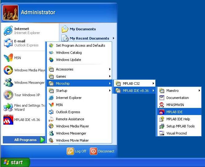
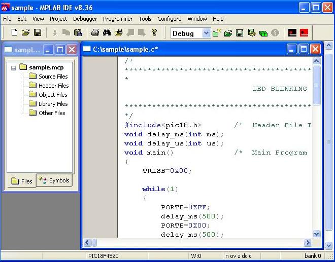
- Step 1: Launch MPLAB IDE
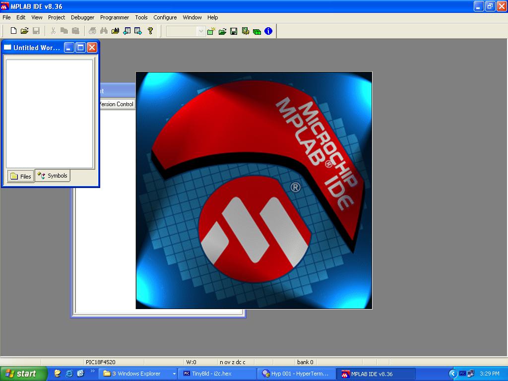
- Step 2: The MPLAB IDE window opens as shown below
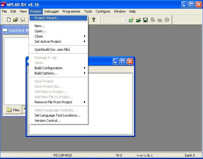
- Step 3: To create a new project, select Project >Project Wizard from menu
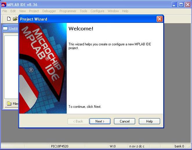
- Step 4: Click next on the Project Wizard window
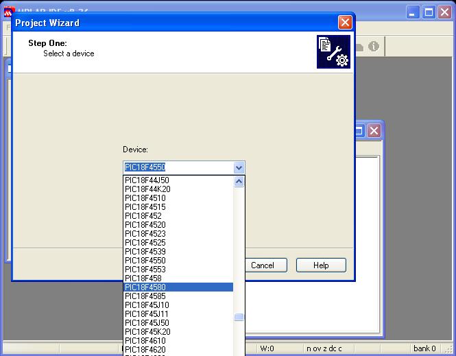
- Step 5: The following window opens. Select PIC18F4550 from the drop-down list and click ‘Next‘
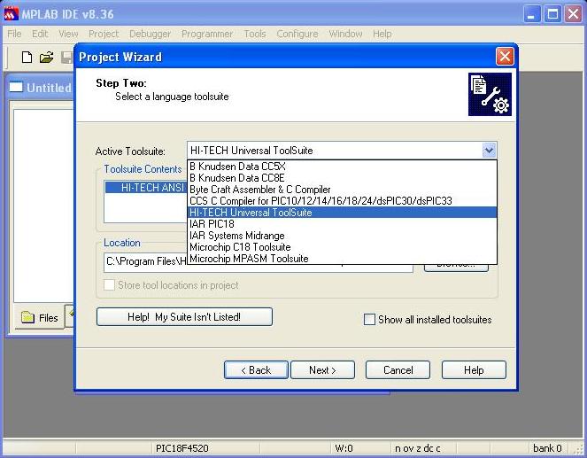
- Step 6: The following window open. Select HI-TECH Universal TOOLSuite as compiler, check the Toolsuite Contents are the same as shown below ,else select and click ‘Next‘
Note:
- To write a program in assembly language, select Microchip MPASM Tool-suite and to write a program in C, select HI-TECH Universal TOOLSuite.
- If a cross marking is shown on the left side of the tool contents, then select that particular tool and browse its corresponding .exe file at the location path provided and click ‘NEXT’ to continue.
- Step 7: Go for Browse, Save the project in a suitable location with appropriate name
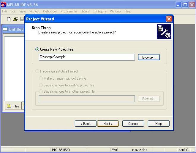
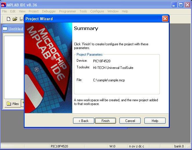
- Step 8: Click Next to the following window open.
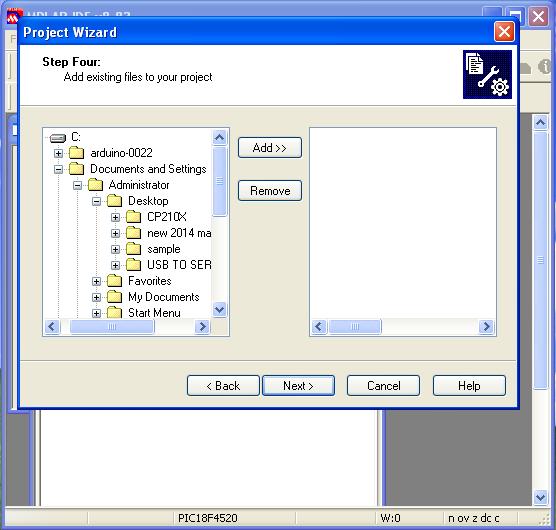
- Step 9: Click Finish to the following window open.Thus create a project with project name ‘Sample‘.
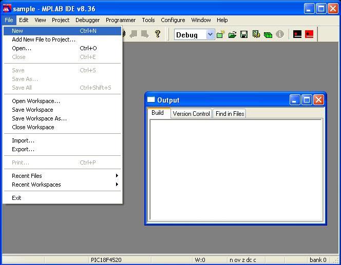
- Step 10: Create a new file either by clicking the New File icon,or by selecting File > New or using keyboard shortcut CTRL + N
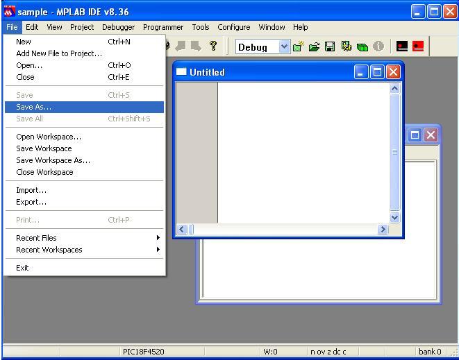
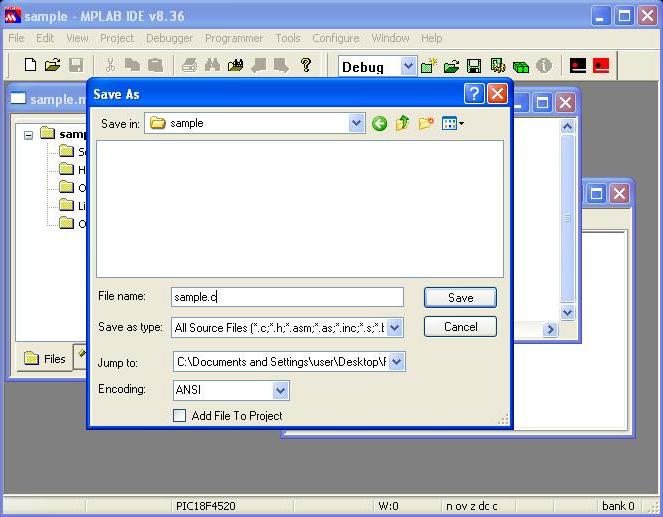
- Step 11: Save the file in the appropriate folder by File >Save as or by save icon
- Step 12: Thus save the file with .c extension
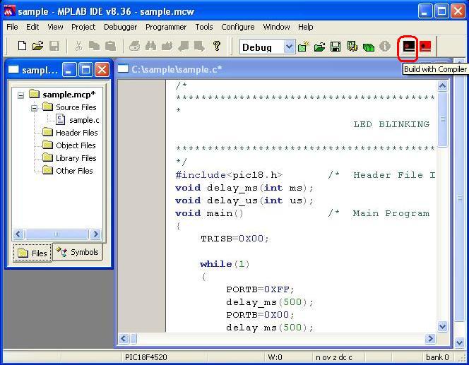
- Step 13: Now type the code in the c file
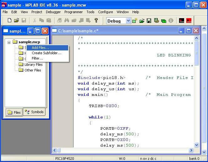
- Step 14: Add the c file to the project by right click over the Source files and select
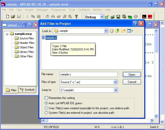
- Step 15: From the following window select the proper c file and click ‘open‘
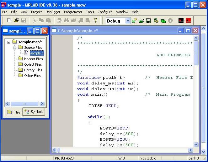
- Step 16: Thus add the c file
- Step 17: Now compile the code by selecting Project <Build or Build with compiler icon as shown below.Errors(if any)get listed in the Build output window.Correct them and build again.
- Step 18: To Specify ROM ranges, select Project >Build Options…>Project>Global>ROM ranges from menu. Type the ROM ranges as shown below . Then click Apply and OK.

- Step 19: The controller can burn using either Pickit2 or serially. If you are using Pickit2, then you should select the proper configuration bits ( you can skip step19 for serial programming). Select configure> configuration bits…untick the option configuration bits set in the code. You can set the bits as shown below. After selecting proper configuration tick the option configuration bits set in the code and build the code.

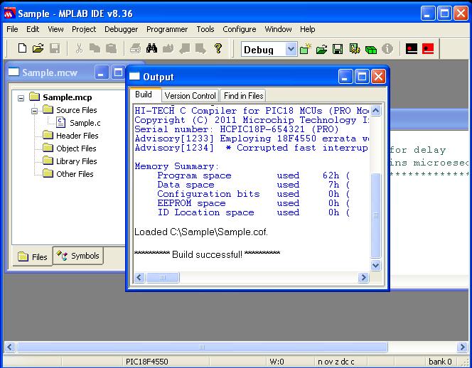
- Step 20: On successful building, the hex file will be generated in the project folder. And output window will be as shown below.
- Step 20: Now the code can be flashed to the controller.
On the board, make sure to do the following jumper connections- Select the power source as USB cable or DC source.
- Select USB or serial port for flashing the code.
 Now power up the board. The power LED on the board glows. Open Tiny Bootloader(Download),
-
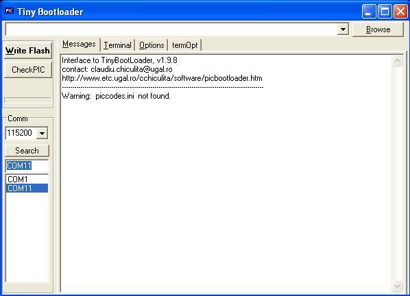
Step 21: Open the Tiny Bootloader
-
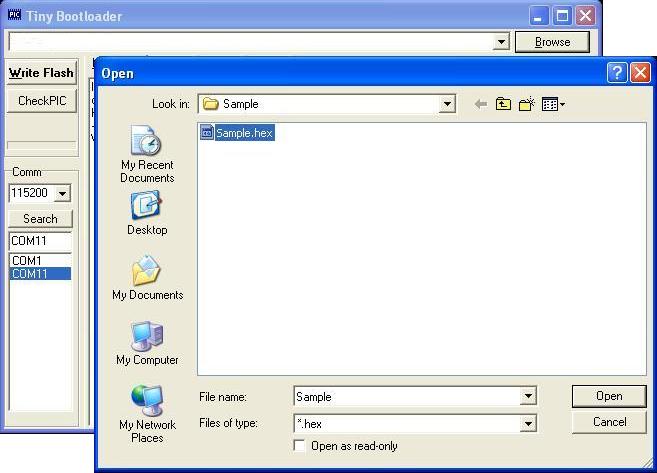
Step 22: Load/Browse the required hex file. A window opens as shown below.
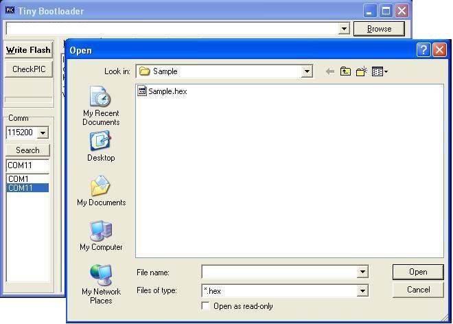
- Step 23: Select the required hex file and click ‘Open’. Select the correct COM port recognized by PC and if its more than COM5 change it to any any lower COM port in Device Manager and select suitable baud rate.
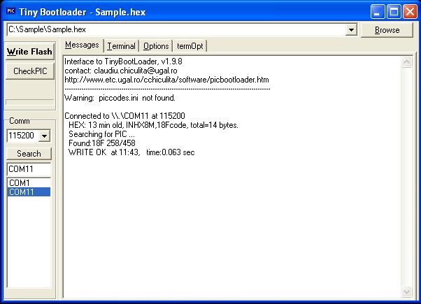
- Step 24: Click Write Flash(in Tiny bootloader) and simultaneously press Reset button in the on-board mini development board. After successfully flashing the code, use controller for the desired purpose.
Topics related to PIC18F4550 Mini Development Board![]()
- PIC18F4550 Mini Development Board – Overview
- PIC18F4550 Mini Development Board – Interfacing LED
- PIC18F4550 Mini Development Board – Interfacing LCD
- PIC18F4550 Mini Development Board – Serial communication(USART)
- PIC18F4550 Mini Development Board – Interfacing Switch
- PIC18F4550 Mini Development Board – Interfacing Buzzer
- PIC 18F4550 Mini Development Board – Interfacing POT(ADC)
- PIC18F4550 Mini Development Board – Interfacing Temperature sensor
- PIC18F4550 Mini Development Board – Interfacing Servo Motor
- PIC18F4550 Mini Development Board – Interfacing μRFID
Resources![]()
- Datasheets
How to buy?![]()
- Click here to buy rhydoLABZ PIC 16F877A Mini Development Board
- Click here to buy rhydoLABZ PIC 18F4520 Mini Development Board
- Click here to buy rhydoLABZ PIC 18F4550 Mini Development Board
- Click here to buy rhydoLABZ PIC 18F4580 Mini Development Board
Support![]() Please share your ideas with us, visit our forum for discussion
Please share your ideas with us, visit our forum for discussion
Leave a Reply
You must be logged in to post a comment.