Servo Controller Hookup Guide
A servo controller is a dedicated board that helps the user to control servos based on the commands sent to it from an external device such as a computer or microcontroller. Using a dedicated servo controller frees up memory on a microcontroller which would be used to constantly update the servos’ positions.
Enables the user to control upto 18 servos with serial commands issued from PC or another Arduino. You can also set various parameters like minimum, maximum, reset angles, speed and save these parameters permanently. You can also enable / disable individual servo as well as set the position.

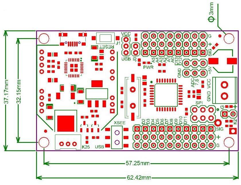
The servo controller is built around the popular chip ATMega 328P running at 16MHz clock controls the servos based on serial commands received. The servos are connected to digital pins 2 to 19 in order [as labelled on the board]. Reset switch is provided to reset the controller.
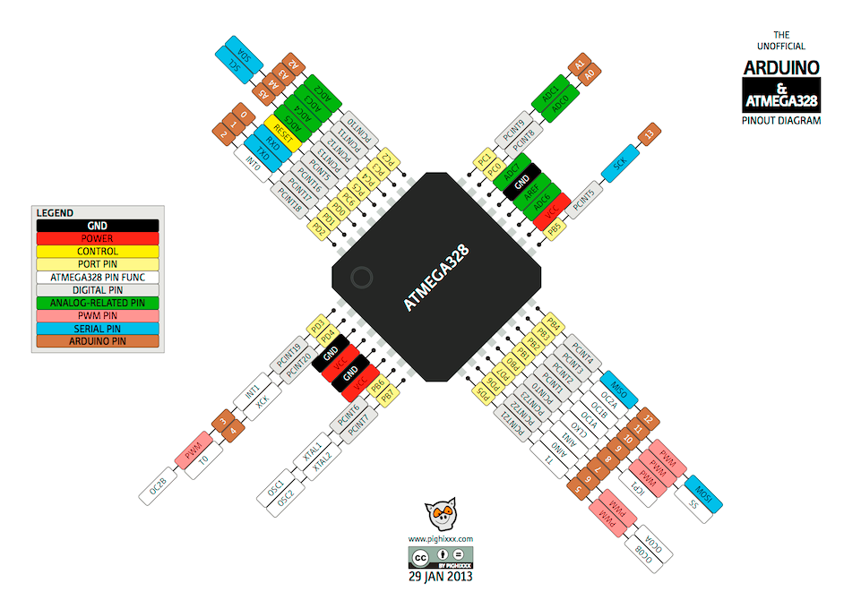 The chip comes with Arduino bootloader which allows you to program serially via USB. The 6-pin ISP connector is also provided.
Powering the board
The board can be powered via on-board micro USB connector, 2 pin berg strip connector [K2] or screw terminal [K4].
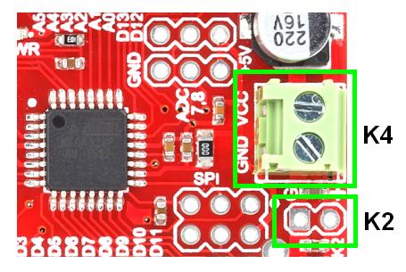
The servo motors are powered directly from the external DC source / Battery connected to 2 pin berg strip connector or screw terminal. It is very important to ensure that the supply voltage used should be compulsorily in the recommended operating voltage range of servo motor you are using
The rest of the board gets powered from external source / USB based on jumper (J1) selection. Once the board is powered, the power indicator LED lits up.
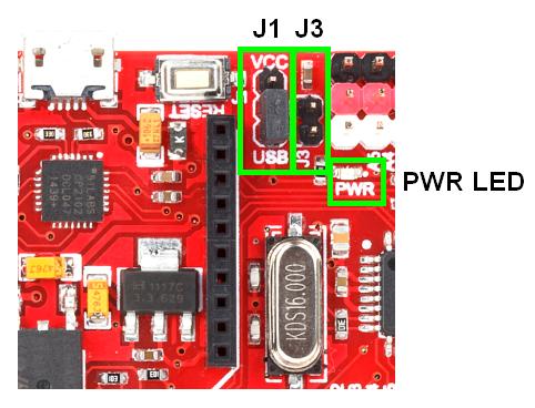
If J1 selects external source as power source, then keep J3 open if the source voltage is >5V. Shorting the jumper shorts the input and output terminals of regulator
To drive servos, take care to power the board with a source that is capable of sourcing enough current otherwise the servos do not work fine.
Plugging the servos
For most RC servos, a 500us long pulse (0.5ms) at 5V would rotate the servo to 0 degrees, a 1500us (1.5ms) long pulse would rotate the servo to 90 degree and a 2500us (2.5ms) pulse corresponds to 180 degrees. This pulse needs to be repeated every ~20ms. These pulses are given by the servo controller to signal pin of servo which in turn moves the servo to corresponding position.
Labelled multi-colour berg strip connectors enable you to plugin the servos with ease. The 18 connectors are laid out as 2 different sections with one section having 10 strips [D2-D11] and the other having 8 strips [D12, D13, A0-A5]. Servo1 (as per software) is connected to D2 and the servos are numbered in anti-clockwise direction to end up with servo18 connected to A5 (D19)
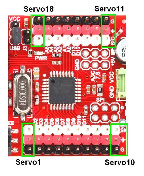
> The White strips are the signal pins
>The Red strips are the Vcc pins
>The Black strips are the Gnd pins
Communicating with the board
- Communicating with PC / Laptop – Via USB / Xbee / 3 pin RMC connector
- The board can communicate with PC via micro USB cable plugged into the micro USB port and the Xbee/USB selector DPDT slide switch pushed to USB side. In this case the PC should automatically detect the servo controller and install the appropriate drivers to let the board appear as a COM port. If your computer does not detect the board, you should manually install the CP2102 chip VCP drivers (based on your operating system)
- The controller has Xbee port with on-board 3.3V regulator and level converter that enables you to plug in XBee / Bluebee directly without any additional circuitry. The orientation of Xbee has been marked for ease of use. The Xbee/USB selector DPDT slide switch pushed to XBEE side. The paired Xbee can be interfaced to PC using an XBee Explorer Dongle
- You can also use a TTL – USB / TTL – RS 232 converter to communicate with the MCU directly via 3-pin RMC connector K25. The port has 3 pins namely TXD, RXD, GND and communicates in 5V level [Programming not possible]
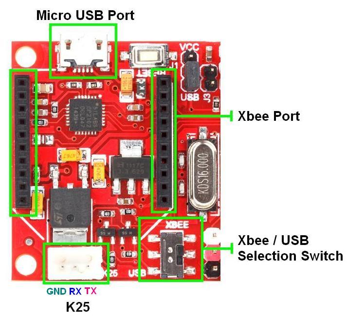
- The board can communicate with PC via micro USB cable plugged into the micro USB port and the Xbee/USB selector DPDT slide switch pushed to USB side. In this case the PC should automatically detect the servo controller and install the appropriate drivers to let the board appear as a COM port. If your computer does not detect the board, you should manually install the CP2102 chip VCP drivers (based on your operating system)
- Communication with another Arduino – The servo controller enables you to control servos from an external Arduino using serial commands. The Arduinos can communicate in 2 ways
- Wirelessly via Xbee / Bluebee
- RMC connector
- Wirelessly via Xbee / Bluebee
ADC6 and ADC7
ADC6 and ADC7 are available only in TQFP and QFN/MLF package and serve as analog inputs to the ADC. These pins are powered from the analog supply and serve as 10-bit ADC channels. In the servo controller, they are taken out (along with 5V & GND pins) on separate 3-pin connectors K17 & K18 which allow you to interface plug in a sensor or monitor battery voltage directly.
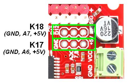
The following code snippet reads the ADC channels A6, A7 and prints them out serially in regular interval.
|
1 2 3 4 5 6 7 8 9 10 11 12 13 14 15 16 17 18 19 20 21 |
int i = 0, j = 0; void setup() { pinMode(A6, INPUT); pinMode(A7, INPUT); Serial.begin(9600); } void loop() { delay(1000); i = analogRead(A6); j = analogRead(A7); Serial.print(i); Serial.print(' '); Serial.println(j); } |
CAUTION! Since the servo controller comes with Arduino bootloader, you can even program the servo controller with your custom code. But in such a case, note that the default firmware will be lost for ever which means that you won’t be able to control your servos with the software.
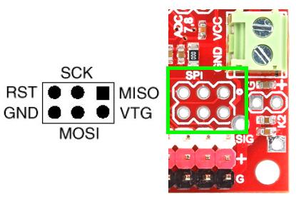
K7 : 6-pin ISP Connector
To bootload the MCU or to program the MCU directly without bootloader. 1st pin is indicated by a white dot.
Command Set
The servo controller works on the basis of the following command set.
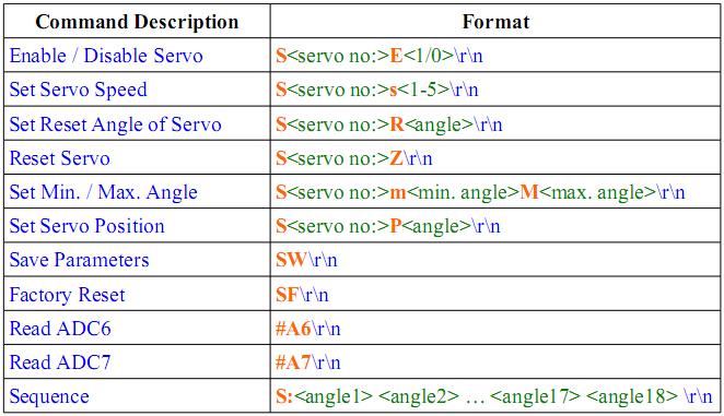
By default, the minimum, maximum and reset angles are 0, 180 and 90 respectively. To set the minimum, maximum and reset angles of the servos 1 &18 and to rotate them, refer the given pattern
S1m40M120\r\n
S18R75\r\n
S1E1\r\n
S18E1\r\n
S1P60\r\n
- Here the min. & max. angles of servo1 are set as 40 and 120 \n the first command (S1m40M120). Since no command is given for servo18, it will retain the default values 0 & 180 respectively.
- The second command sets the reset position of servo18 as 75 (S18R75). Since no command is given for servo1, it will retain the default value of 90.
- The 3rd and 4th commands enable servo1 & servo18 respectively (S1E1 & S18E1). If this command is not used, then the servo won’t rotate
- The fifth command (S1P60) sets servo1 to 60 degree position
The servo controller comes with a software that enables the user to control the servo motors with ease. This Wiki page explains in detail how to use the software.
Dimension
Resources
Shop With Us
- Servo Controller
- Servo Motors
- USB A-microB Cable

Leave a Reply
You must be logged in to post a comment.