ARM LPC2138/48 Mini Development Board – UART0 Interfacing
LPC2138/48 has two UART modules namely UART0 and UART1. It has only asynchronous (no clock connection) mode of operation. For UART0 communication transmission & reception pins are respectively P0.0 & P0.1.
In the mini development board, UART0 can communicate through
- USB port via CP2102
- Serial port via MAX232
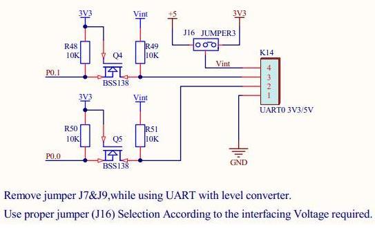
- RMC connector K14(GND,TXD0,RXD0,Vout) in 3.3V/5V levels
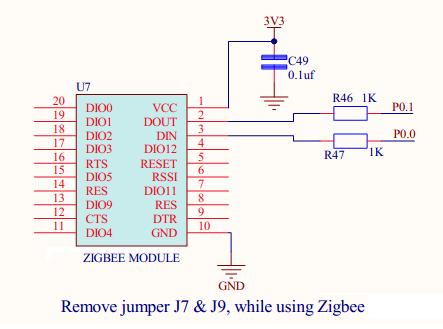
- Zigbee
Schematic![]()
Note:
- UART0 communication via USB/serial port is selected using jumpers J7 & J9
- While using UART0 for communication, PROGRAMMER switch should be in manual mode.
- Through RMC connector, UART0 can be used in two voltage levels of 3V3/5V which can be selected by jumper J16
- While using Zigbee, remove jumpers J7 & J9
Sample Code![]()
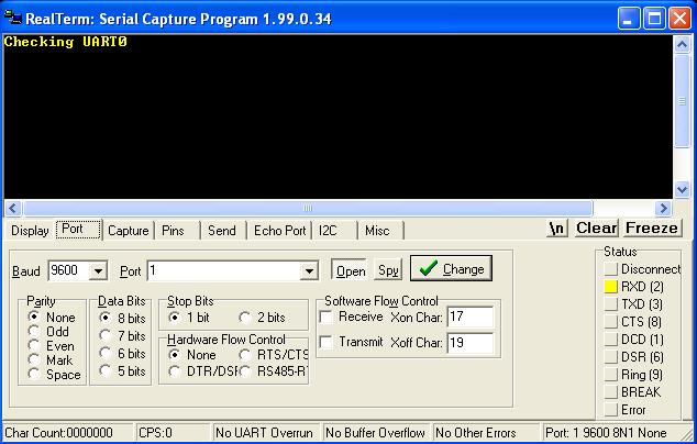
Sample code to test both transmission & reception of UART0 is given below. Initially the string “Checking UART0” gets transmitted and on receiving a character, it gets retransmitted.
|
1 2 3 4 5 6 7 8 9 10 11 12 13 14 15 16 17 18 19 20 21 22 23 24 25 26 27 28 29 30 31 32 33 34 35 36 37 38 39 40 41 42 43 44 45 46 47 48 49 50 51 52 53 54 55 56 57 58 59 60 61 62 63 64 65 66 67 68 69 70 71 72 73 74 75 76 77 78 79 80 81 |
/************************************************************************* HEADER FILE **************************************************************************/ #include<lpc21xx.h> /************************************************************************* * Function : UART_Init * * * * Description : Function to initialize UART0 * * * * Parameters : None * **************************************************************************/ void Uart_Init(void) { U0LCR = 0X83; /* 8 bit character length, DLAB access enabled */ U0DLL = 0XC3; /* The UART0 Divisor Latch LSB Register, and */ U0DLM = 0X00; /* U0DLM loaded with value for 9600 baudrate */ U0LCR = 0X03; /* DLAB access disabled */ } /************************************************************************* * Function : UART_Data * * * * Description : Function to transmit single character * * * * Parameters : data - character to be transmitted * **************************************************************************/ void Uart_Data(unsigned char data) { U0THR = data; /* Load the character to Transmit Holding register */ /* THRE set when transmission complete */ while((U0LSR & 0X20)!= 0X20); } /************************************************************************* * Function : UART_String * * * * Description : Function to transmit string * * * * Parameters : String to be transmitted * **************************************************************************/ void Uart_String(unsigned char *dat) { while(*dat!='\0') /* Check for termination character */ { Uart_Data(*dat); /* Transmit the character */ dat++; /* Increment the pointer */ } } /************************************************************************* * Function : PORT_Initial * * * * Description : Function to initialize ports * * * * Parameters : None * **************************************************************************/ void Port_Initial(void) { PINSEL0 = 0x00000005; /* Functions TXD & RXD for P0.0 & P0.1 resp. */ } /************************************************************************* MAIN FUNCTION **************************************************************************/ int main() { Port_Initial(); /* Initialize the ports */ Uart_Init(); /* Initialize UART0 */ Uart_String("Checking UART0"); /* Transmit the string */ while(1) { if((U0LSR&0X01)==0X01) /* RDR set when U0RBR contains data */ { U0THR = U0RBR; /* Transmit the received character */ while((U0LSR&0X20)!=0X20); } } } /************************** END OF PROGRAM *****************************/ |
Output![]() The following screenshots explain how to test the sample code using RealTerm (click to download).
The following screenshots explain how to test the sample code using RealTerm (click to download).
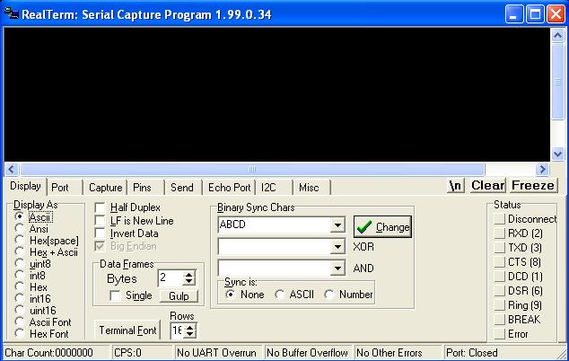
- Step 1: Open RealTerm

- Step 2: RealTerm opens as shown below
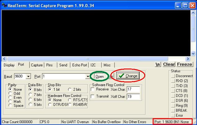
- Step 3: Go to ‘Port’ option, set correct baudrate (which is set as 9600 in the sample code) and correct port
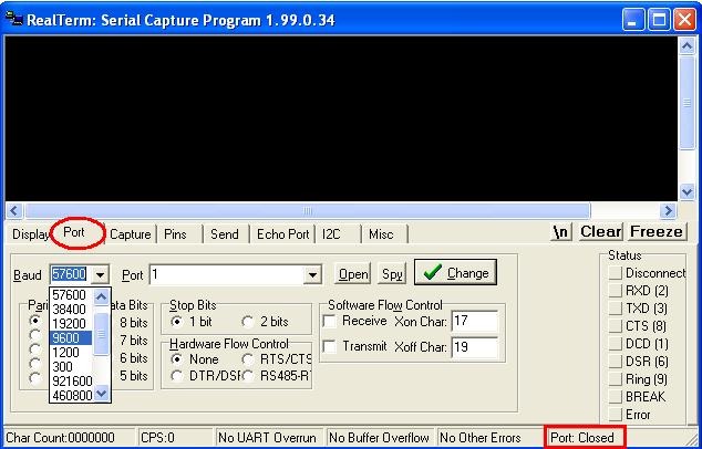
- Step 4: Click ‘Change’ (encircled in red) to apply the changes. Now check the status of Port. If it is closed, click ‘Open’ button (encircled in green) to open it.
- Step 5: The data transmitted from the board can be viewed as shown below.
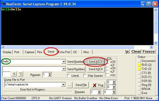
- Step 6: To check reception, go to Send option, type the string in the space provided(encircled in green) and click Send ASCII button. The first “hello” in green colour is transmitted from PC & that in yellow colour is retransmitted by the controller
Topics related to ARM LPC2138/48 Mini Development Board![]()
- ARM LPC2138/48 Mini Development Board – Overview
- ARM LPC2138/48 Mini Development Board – LED Interfacing
- ARM LPC2138/48 Mini Development Board – LCD Interfacing
- ARM LPC2138/48 Mini Development Board – UART0 Interfacing
- ARM LPC2138/48 Mini Development Board – UART1 Interfacing
- ARM LPC2138/48 Mini Development Board – Switches Interfacing
- ARM LPC2138/48 Mini Development Board – BUZZER Interfacing
- ARM LPC2138/48 Mini Development Board – POT Interfacing (ADC)
- ARM LPC2138/48 Mini Development Board – Temperature Sensor Interfacing(ADC)
- ARM LPC2138/48 Mini Development Board – Interfacing Servo motor
- ARM LPC2138/48 Mini Development Board – Internal Real Time Clock (RTC)
- ARM LPC2148 Mini Development Board – USB Interfacing (Human Interface Device)
Resources![]()
- Softwares
- Datasheets
How to buy?![]()
- Click here to buy rhydoLABZ ARM LPC2129 Development board-Mini
- Click here to buy rhydoLABZ ARM LPC2138 Development Board-Mini
- Click here to buy rhydoLABZ ARM LPC2148 Development Board-Mini
Support![]()
Please share your ideas with us, visit our forum for discussion
Leave a Reply
You must be logged in to post a comment.