PIC18F4580 – Serial communication(USART)
The USART module of PIC PIC18F4580 uses pins RC7 & RC6 for reception & transmission respectively. The mini development board can communicate with PC/external modules through
- USB port via CP2102
- Serial port via MAX232
- RMC connector K15 in 5V level
- RMC connector K17 in 3.3V level
Besides, USART is also used for interfacing Zigbee & RFID reader.
Schematic![]()


Note:
- 3V3 USART communication through K17 is possible only if the jumpers J13 and J14 (XBTX, XBRX) are shorted.
- For communicating through K15 & K17, remove jumpers J3 & J4
Sample Code![]()
The sample code to check USART module is given below. Initially the letter ‘A’ gets transmitted and upon receiving a character, the same gets retransmitted.
|
1 2 3 4 5 6 7 8 9 10 11 12 13 14 15 16 17 18 19 20 21 22 23 24 25 26 27 28 |
/********************************************************************** HEADER FILE ***********************************************************************/ #include<pic18.h> /********************************************************************** MAIN FUNCTION ***********************************************************************/ void main() { TRISC = 0x80; /* RC6=0(TX)-o/p, RC7(RX)-i/p */ SPBRG = 0x81; /* Serial Port Baud Rate Generator for 9600 */ TXSTA = 0X24; /* TXEN=1, SYNC=0, BRGH=1 */ RCSTA = 0X90; /* Reception Enable (SPEN=1,CREN=1) */ TXREG = 'A'; /* Load the character to be transmitted */ while(!TRMT); /* Wait here till transmission is complete */ while(1) { if(RCIF==1) { RCIF=0; /* Clear Receive interrupt flag bit */ TXREG = RCREG; /* Retransmit the received character */ while(!TRMT); /* Wait here till transmission is complete */ } } } /************************ END OF PROGRAM ****************************/ |
Output![]()
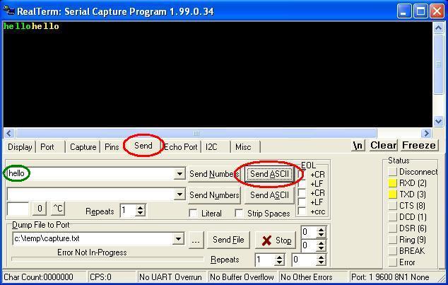
The following screenshots explain how to test the sample code using RealTerm (click to download).
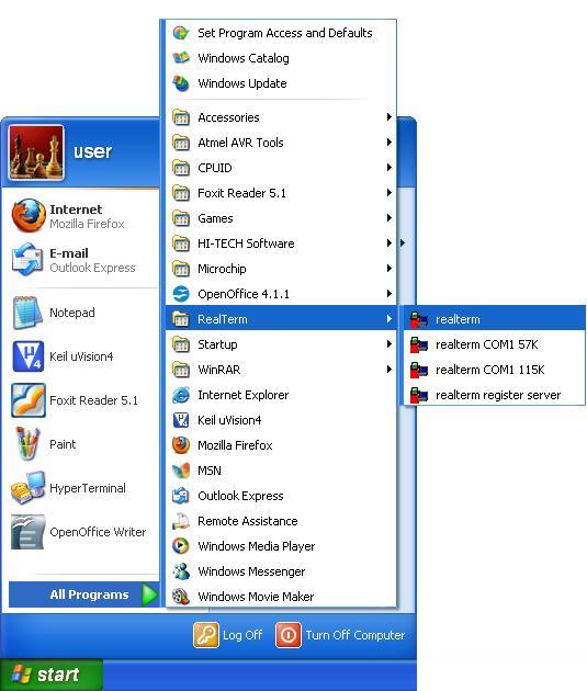
- Step 1: Open RealTerm
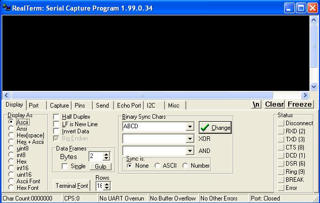
- Step 2: RealTerm opens as shown below
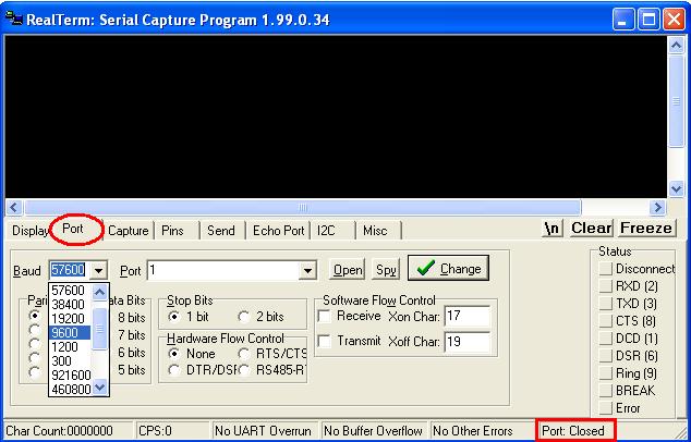
- Step 3: Go to ‘Port’ option, set correct baudrate (which is set as 9600 in the sample code) and correct port
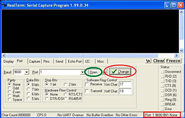
- Step 4: Click ‘Change’ (encircled in red) to apply the changes. Now check the status of Port. If it is closed, click ‘Open’ button (encircled in green) to open it.
- Step 5: To check reception, go to Send option, type the string in the space provided (encircled in green) and click Send ASCII button. The first “hello” in green colour is transmitted from PC & that in yellow colour is retransmitted by the controller
Topics related to PIC18F4580 Mini Development Board![]()
- PIC18F4580 Mini Development Board – Overview
- PIC18F4580 Mini Development Board – Interfacing LED
- PIC18F4580 Mini Development Board – Interfacing LCD
- PIC18F4580 Mini Development Board – Serial communication(USART)
- PIC18F4580 Mini Development Board – Interfacing Switch
- PIC18F4580 Mini Development Board – Interfacing Buzzer
- PIC 18F4580 Mini Development Board – Interfacing POT(ADC)
- PIC18F4580 Mini Development Board – Interfacing Temperature sensor
- PIC18F4580 Mini Development Board – Interfacing Servo Motor
- PIC18F4580 Mini Development Board – Interfacing μRFID
- PIC18F4580 Mini Development Board – Interfacing CAN
Resources![]()
- Datasheets
How to buy?![]()
- Click here to buy rhydoLABZ PIC 16F877A Mini Development Board
- Click here to buy rhydoLABZ PIC 18F4520 Mini Development Board
- Click here to buy rhydoLABZ PIC 18F4550 Mini Development Board
- Click here to buy rhydoLABZ PIC 18F4580 Mini Development Board
Support![]() Please share your ideas with us, visit our forum for discussion
Please share your ideas with us, visit our forum for discussion
Leave a Reply
You must be logged in to post a comment.