AVR ATmega32 Mini Development Board – Interfacing Servo Motor
Servos have simple electrical interface – they have 3 wires, one for power, one for ground and the other for the pulse train. Once the servo is powered, the signal wire is ready to receive signal in the form of pulse width modulation (PWM) from an external source.
The signal expects to be updated every 20 ms with a pulse between 0.5ms and 2.5ms. With a 1.5 ms pulse, the servo motor will be at the natural 90° position. With a 0.5 ms pulse, the servo will be at the 0° position, and with a 2.5 ms pulse, the servo will be at 180°. You can obtain the full range of motion by updating the servo with a value in between. AVR ATmega32 mini development board has a dedicated connector K11 to interface Servo motor. Regulated 5V is available on power supply pin and the signal pin is connected at the port pin PC6.
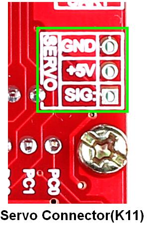
Note: Use adapter for powering since USB doesn’t provide required current.
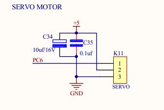
Schematic![]()
 Sample Code
![]()
Sample code to check servo motor is given below. Upon code execution, the servo wipes continuously.
|
1 2 3 4 5 6 7 8 9 10 11 12 13 14 15 16 17 18 19 20 21 22 23 24 25 26 27 28 29 30 31 32 33 34 35 36 37 38 39 40 41 42 43 44 45 46 47 48 49 50 51 52 53 54 55 56 57 58 59 60 61 62 63 64 65 66 67 68 69 70 71 72 73 74 75 76 77 78 79 80 81 82 83 84 85 86 87 88 89 90 91 92 93 94 95 96 |
/************************************************************************************ HEADER FILES *************************************************************************************/ #define F_CPU 8000000UL #include<avr/io.h> /* Header File Inclusion */ #include<avr/interrupt.h> /* Interrupt File Inclusion */ #include<util/delay.h> /* Delay File Inclusion */ /************************************************************************************ VARIABLE DECLARATIONS *************************************************************************************/ volatile unsigned char Timer_Count; unsigned char Servo_Angle = 10; unsigned char Servo_Value = 0; unsigned char k = 0; volatile unsigned char count = 0; /************************************************************************************ FUNCTION DECLARATIONS *************************************************************************************/ unsigned char Convert_Angle(unsigned char k); /************************************************************************************ MAIN FUNCTION *************************************************************************************/ int main() { DDRC = 0X40; /* PC6 pin set as output for servo */ TCCR0 = 0X02; /* Prescalar is 8 */ TCNT0 = 0XEB; /* Timer count for 20micro second */ TIMSK = 0X01; /* Timer0 interrupt enable */ SREG = 0X80; /* Global interrupt enable */ while(1) { for(k=0; k<=150; k++) /* Loop for angle increment */ { /* Convert angle to count */ Servo_Value = Convert_Angle(Servo_Angle++); _delay_ms(10); } for(k=0; k<=150; k++) /* Loop for angle decrement */ { /* Convert angle to count */ Servo_Value = Convert_Angle(Servo_Angle--); _delay_ms(10); } } } /************************************************************************************ INTERRUPT SERVICE ROUTINE *************************************************************************************/ ISR(_VECTOR(11)) { TIFR=0X01; /* TOV0 flag.clear by writing logic 1 */ Timer_Count++; /* Variable for count overflow */ if( Timer_Count < 125 ) /* Count for 180 degree i.e. 2.5ms */ TCNT0=0XEB; /* Load timer value for 20us pulse */ if( Timer_Count == Servo_Value ) PORTC &=~(1<<6); /* Clearing servo pin */ if( Timer_Count >= 125 ) /* Angle greater than 180 */ { TCNT0=0X97; /* 3.5 ms delay */ TCCR0=0X04; /* Set pin connected to servo */ } if( Timer_Count == 130 ) /* 17.5ms(5*3.5) ie:2.5+17.5=20mS */ { PORTC=0X40; /* Set pin connected to servo */ TCCR0=0X02; /* CS01=1, prescalar is 8 */ TCNT0=0XEB; /* Load 20us pulse */ Timer_Count=0; /* Clear timer count */ } } /************************************************************************************ * Function : Convert_Angle * * * * Description : Function to calculate timer count for angle * * * * Parameters : k, contains the angle to be convert * *************************************************************************************/ unsigned char Convert_Angle(unsigned char k) { unsigned char timer_value; int temp; temp=k*5; timer_value = temp/9; /* Timer value=(100/180)+25i.e(5/9)+25 */ timer_value=timer_value+25; _delay_ms(3); return timer_value; /* Return timer value */ } /**************************** END OF PROGRAM ***************************************/ |
Topics related to AVR ATmega32 Mini Development Board![]()
- AVR ATmega32 Mini Development Board – Overview
- AVR ATmega32 Mini Development Board – Interfacing LED
- AVR ATmega32 Mini Development Board – Interfacing LCD
- AVR ATmega32 Mini Development Board – Serial communication(USART)
- AVR ATmega32 Mini Development Board – Interfacing Switch
- AVR ATmega32 Mini Development Board – Interfacing Buzzer
- AVR ATmega32 Mini Development Board – Interfacing POT(ADC)
- AVR ATmega32 Mini Development Board – Interfacing Temperature sensor
- AVR ATmega32 Mini Development Board – Interfacing Servo Motor
- AVR ATmega32 Mini Development Board – Interfacing μRFID
Resources![]()
How to buy?![]()
- Click here to buy rhydoLABZ AVR ATmega16 Development Board-Mini
- Click here to buy rhydoLABZ AVR ATmega32 Development Board-Mini
- Click here to buy rhydoLABZ Servo motor
Support![]() Please share your ideas with us, visit our forum for discussion
Please share your ideas with us, visit our forum for discussion
Leave a Reply
You must be logged in to post a comment.