AT89S52 Mini Development Board – Serial Communication
UART (Universal Asynchronous Receiver Transmitter) is the hardware component, available in almost every microcontroller, used to transmit a byte of data serially through a single wire. To perform communication between a PC and the controller UART, the AT89S52 Development Board (Mini) has following interfaces.
- RS232 interface over DB9 connector
- USB interface over mini USB connector (MINI 5B)
- Wireless connectivity over ZigBee
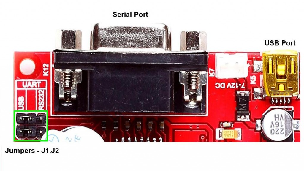
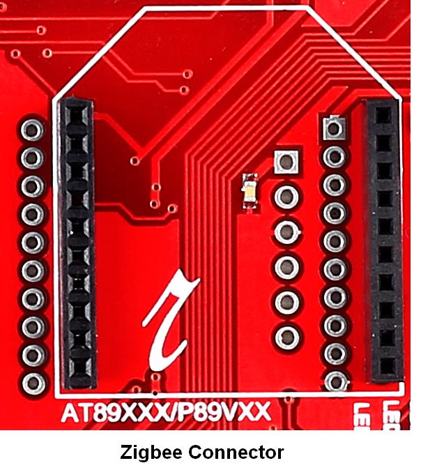
RS232.USB.Zigbee images
Additionally, communication between the controller and other peripheral modules (+5V and +3.3V) can be carried over any of the following two options.
- 5V connection over RMC connector
- 3V3 connection over RMC connector
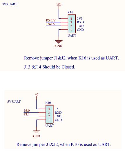
5V.3V3 UART image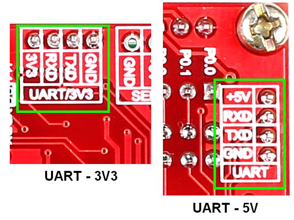
Note :
- USART communication via USB/serial port is selected using jumpers J1 & J2
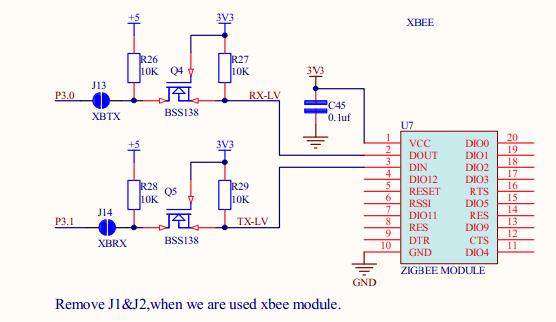
- Short jumpers J13 & J14 while using 3V3 USART / Zigbee
- Remove jumpers J1 & J2 while using Zigbee / RFID / UART (3V3/ 5V)
Schematic![]()
The RS232 interface wields the capabilities of MAX232 while the USB interface utilizes the power of a CP2102. Desired interface for communication can be selected using the jumper connection provided on board. The code given below can be used to test the UART communication ie; up on transmitting a data the same data will be received back.
Sample Code![]()
|
1 2 3 4 5 6 7 8 9 10 11 12 13 14 15 16 17 18 19 20 21 22 23 24 25 26 27 28 29 30 31 32 33 34 35 36 37 38 39 40 41 42 43 44 |
/********************************************************************** HEADER FILE ***********************************************************************/ #include <REGX52.H> /********************************************************************** VARIABLE DECLARATIONS ***********************************************************************/ char receive=0; char trans2[]="->Received\r\n"; int i=0; /********************************************************************** MAIN FUNCTION ***********************************************************************/ void main() { TMOD = 0X21; /* Baudrate from Timer1 in Auto-Reload mode */ SCON = 0X50; /* UART Mode1 and REN set to enable Reception */ TF1 = 0; /* Clear TIMER1 overflow flag */ TR1 = 0; /* Clear TR1 to turn off timer 1 */ TH1 = 0XFD; /* Load value to Timer 1 High Byte Register */ TL1 = 0XFD; /* Load value to Timer 1 Low Byte Register */ TR1 = 1; /* Set TR1 to turn on timer 1 */ while(1) { if(RI==1) /* Set by hardware at the end of the 8th bit */ { RI = 0; receive = SBUF; /* Store the received value in a variable */ SBUF = receive; /* Transmit the received data */ while(TI==0); /* Set at the end of 8th bit transmission */ TI = 0; for(i=0; trans2[i]!='\0'; i++) /* Transmitting Array trans2 */ { SBUF = trans2[i]; while(TI==0); TI = 0; } } } } /************************ END OF PROGRAM ****************************/ |
Output![]()
Flash the code into the controller and connect it to PC using suitable interface.. Various steps to check the output using RealTerm are given below.
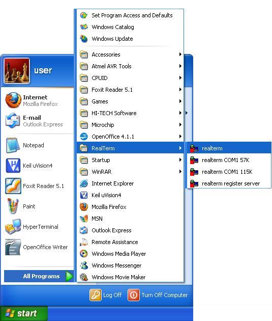
- Step 1: Launch RealTerm
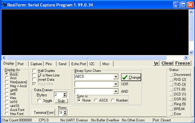
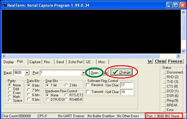
- Step 2: RealTerm opens as shown below
- Step 3: Go to ‘Port’ option, set correct baudrate (which is set as 9600 in the sample code) and give correct port number.
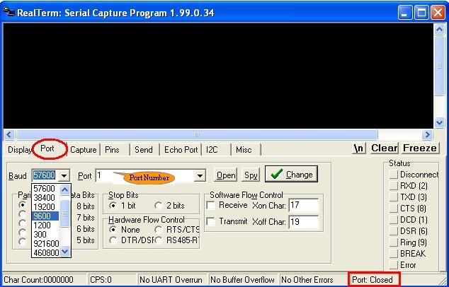
- Step 4: Click ‘Change’ (encircled in red) to apply the changes. Now check the status of Port. If it is closed, click ‘Open’ button (encircled in green) to open it.
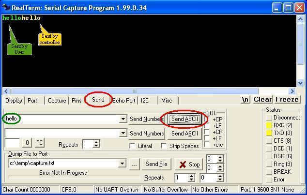
- Step 5: To check reception, go to Send option, type the string in the space provided(encircled in green) and click Send ASCII button. The first “hello” in green colour is transmitted from PC & that in yellow colour is retransmitted by the controller
Topics related to AT89S52 Mini Development Board![]()
- AT89S52 Mini Development Board – Overview
- AT89S52 Mini Development Board – LED Interfacing
- AT89S52 Mini Development Board – LCD Interfacing
- AT89S52 Mini Development Board – Serial communication
- AT89S52 Mini Development Board – EEPROM Interfacing
- AT89S52 Mini Development Board – Buzzer Interfacing
- AT89S52 Mini Development Board – Servo Motor Interfacing
- AT89S52 Mini Development Board – Switch Interfacing
- AT89S52 Mini Development Board – RFID Interfacing
Resources![]()
How to buy?![]()
- Click here to buy the rhydoLABZ AT89S52 Mni Development Board (Mini) V1.01
- Click here to buy the rhydoLABZ AT89S52 Development Board
- Click here to buy the rhydoLABZ AT89S52-24PU Microcontroller
- Click here to buy the rhydoLABZ ATMEL 89SXX ISP Programmer (RS232)
Support![]() Please share your ideas with us, visit our forum for discussion
Please share your ideas with us, visit our forum for discussion
Leave a Reply
You must be logged in to post a comment.