AT89S52 Mini Development Board – LCD Interfacing
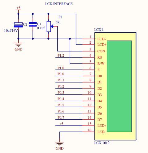
The AT89S52 Mini Development Board includes on the board hardware support for 2×16 LCD display in 8bit mode configuration. A male berg strip connector, with a total of 16 pins, is provided next to the controller base. The alphanumeric 2×16 LCD display can be plugged on this connector. The 16 pin configured berg strip, provided to meet the hardware demands of the LCD module, connects the control lines of the LCD module to PORT1 GPIO pins of the controller RS(P1.2), R/W(GND), E(P1.0) and the data lines to the PORT0 GPIO pins D0 – D7(P0.0 – P0.7). It connects the contrast pin of the module to an SMD potentiometer so that the contrast can be varied on users wish. The communication between controller and the LCD module is performed in a 8-bit mode.Thus the sample code below shows the code for LCD Display.
 Schematic
![]()
Sample Code![]()
|
1 2 3 4 5 6 7 8 9 10 11 12 13 14 15 16 17 18 19 20 21 22 23 24 25 26 27 28 29 30 31 32 33 34 35 36 37 38 39 40 41 42 43 44 45 46 47 48 49 50 51 52 53 54 55 56 57 58 59 60 61 62 63 64 65 66 67 68 69 70 71 72 73 74 75 76 77 78 79 80 81 82 83 84 85 86 87 88 89 90 91 92 93 94 95 |
/************************************************************************* HEADER FILES **************************************************************************/ #include <REGX52.H> #define LCD_PORT P0 #define EN P1_0 #define RS P1_2 /************************************************************************* FUNCTION DECLARATIONS **************************************************************************/ void LCD_Command(char); void LCD_Data(char); void Delay_us(int Delay); /************************************************************************* VARIABLE DECLARATIONS **************************************************************************/ char dis1[] = "rhydoLABZ"; char dis2[] = "Cochin"; int i=0; /************************************************************************* MAIN FUNCTION **************************************************************************/ void main() { LCD_Command(0x30); /* LCD Specification Command */ Delay_us(5); LCD_Command(0x30); /* LCD Specification Command */ Delay_us(5); LCD_Command(0x30); /* LCD Specification Command */ Delay_us(5); LCD_Command(0x38); /* Double Line Display Command */ LCD_Command(0x06); /* Auto Increment Location Address Command */ LCD_Command(0x0C); /* Display ON Command */ LCD_Command(0x01); /* Clear Display Command */ Delay_us(200); LCD_Command(0x81); /* LCD Location */ for(i=0; dis1[i]!='\0'; i++) LCD_Data(dis1[i]); LCD_Command(0xC3); /* LCD Location */ for(i=0; dis2[i]!='\0'; i++) LCD_Data(dis2[i]); while(1); } /************************************************************************* * Function : LCD_Command * * * * Description : Function to send a command to LCD * * * * Parameters : value - command to be sent * **************************************************************************/ void LCD_Command(char value) { RS = 0; /* RS-0(command register) */ EN = 1; /* E-1(Enable pin high) */ LCD_PORT = value; /* Write the command to data lines */ Delay_us(5); EN = 0; /* E-0(Enable pin low) */ } /************************************************************************* * Function : LCD_Data * * * * Description : Function to display single character on LCD * * * * Parameters : value - character to be displayed * **************************************************************************/ void LCD_Data(char value) { RS = 1; /* RS-1(data register) */ EN = 1; /* E-1(Enable pin high) */ LCD_PORT = value; /* Write the character to data lines */ Delay_us(5); EN = 0; /* E-0(Enable pin low) */ } /************************************************************************* * Function : Delay_us * * * * Description : Function for 1 microsecond delay * * * * Parameter : us - delay in microseconds * **************************************************************************/ void Delay_us(int Delay) { while((--Delay)!=0); } /*************************** END OF PROGRAM ****************************/ |
Topics related to AT89S52 Mini Development Board![]()
- AT89S52 Mini Development Board – Overview
- AT89S52 Mini Development Board – LED Interfacing
- AT89S52 Mini Development Board – LCD Interfacing
- AT89S52 Mini Development Board – Serial communication
- AT89S52 Mini Development Board – EEPROM Interfacing
- AT89S52 Mini Development Board – Buzzer Interfacing
- AT89S52 Mini Development Board – Servo Motor Interfacing
- AT89S52 Mini Development Board – Switch Interfacing
- AT89S52 Mini Development Board – RFID Interfacing
Resources![]()
How to buy?![]()
- Click here to buy the rhydoLABZ AT89S52 Mni Development Board (Mini) V1.01
- Click here to buy the rhydoLABZ AT89S52 Development Board
- Click here to buy the rhydoLABZ AT89S52-24PU Microcontroller
- Click here to buy the rhydoLABZ ATMEL 89SXX ISP Programmer (RS232)
Support![]() Please share your ideas with us, visit our forum for discussion
Please share your ideas with us, visit our forum for discussion
Leave a Reply
You must be logged in to post a comment.