AT89S52 Mini Development Board – Switch Interfacing
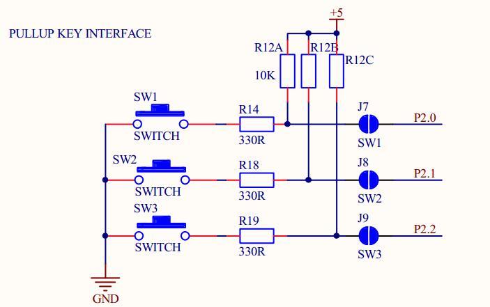
AT89S52 Mini Development Board has 3 Switches (SW1,SW2 & SW3) connected to port pins P2.0, P2.1 & P2.2 via jumpers J7, J8 & J9respectively. On shorting these jumpers, the switches can be used as pull_up keys and if the jumpers are left open, then the port pins can be used independently. Sample code of switch interfacing via UART and LCD display is shown below separately.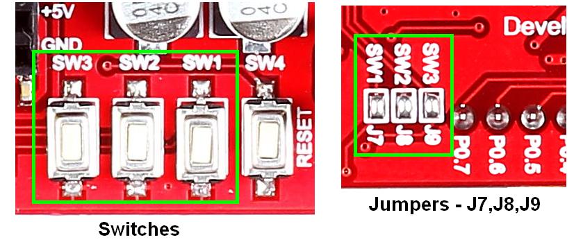 Schematic
![]()
 Sample Code
![]() Switch Interfacing via UART – in the code, switch press is detected by polling and upon pressing a switch, its name gets transmit. In circuit pull-ups has been provided to all three switches.
Switch Interfacing via UART – in the code, switch press is detected by polling and upon pressing a switch, its name gets transmit. In circuit pull-ups has been provided to all three switches.
|
1 2 3 4 5 6 7 8 9 10 11 12 13 14 15 16 17 18 19 20 21 22 23 24 25 26 27 28 29 30 31 32 33 34 35 36 37 38 39 40 41 42 43 44 45 46 47 48 49 50 51 52 53 54 55 56 57 58 59 60 61 62 63 64 65 |
/***************************************************************** * Header File * ******************************************************************/ #include <REGX52.H> /*================================================================= Pull Up key Definitions =================================================================*/ #define SW1 P2_0 #define SW2 P2_1 #define SW3 P2_2 /*================================================================= Function Declerations =================================================================*/ void uart_initial(void); void uart_send(const char *dat); /*================================================================= Main Program =================================================================*/ void main() { uart_initial(); while(1) { if(SW1==0) {while(!SW1); uart_send("Pressed Switch 1 \r\n");} /* Switch 1 Check */ if(SW2==0) {while(!SW2); uart_send("Pressed Switch 2 \r\n");} /* Switch 2 Check */ if(SW3==0) {while(!SW3); uart_send("Pressed Switch 3 \r\n");} /* Switch 3 Check */ } } /*================================================================= * Function : uart_initial * Description : Function initialize UART * Parameters : None =================================================================*/ void uart_initial(void) { TMOD=0X21; SCON=0X50; TF1=0; TR1=0; TH1=0XFD; TL1=0XFD; TR1=1; } /*================================================================== * Function : usart_send * Description : Function to send Key Values Through USART * Parameters : data, contains key number to send ==================================================================*/ void uart_send(const char *dat) { while(*dat!='\0') { SBUF=*dat; while(TI==0); TI=0; dat++; } } |
Output![]()
Flash the code into the controller and connect it to PC using suitable interface.. Various steps to check the output using RealTerm are given below.
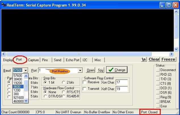
- Step 1: Launch RealTerm
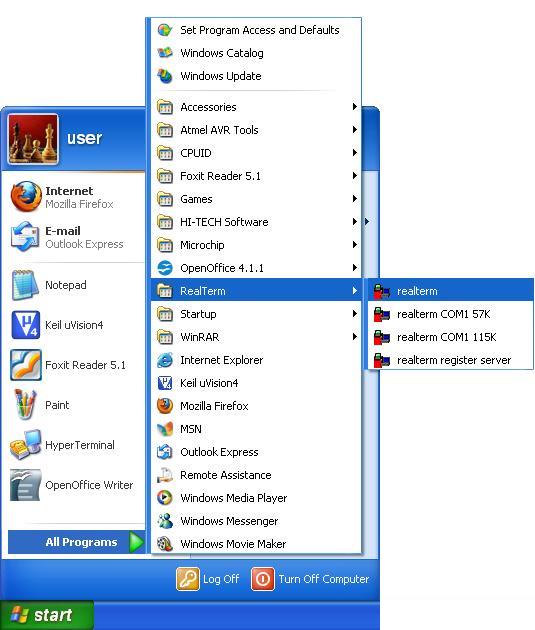
- Step 2: RealTerm opens as shown below
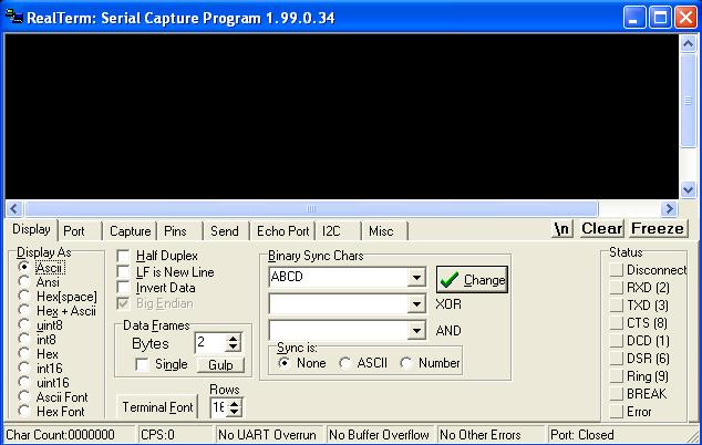
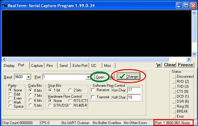
- Step 3: Go to ‘Port’ option, set correct baudrate (which is set as 9600 in the sample code) and give correct port number.
- Step 4: Click ‘Change’ (encircled in red) to apply the changes. Now check the status of Port. If it is closed, click ‘Open’ button (encircled in green) to open it.
- Step 5:Now go for pressing the pull_up keys, when press switch output in real term can be viewed as shown below .

Sample code![]() Switch Interfacing via LCD display – in the code, switch press is detected by polling and upon pressing a switch, its name(SW1/ SW2 /SW3) gets displayed on the LCD. In circuit pull-ups has been provided to all three switches.
Switch Interfacing via LCD display – in the code, switch press is detected by polling and upon pressing a switch, its name(SW1/ SW2 /SW3) gets displayed on the LCD. In circuit pull-ups has been provided to all three switches.
|
1 2 3 4 5 6 7 8 9 10 11 12 13 14 15 16 17 18 19 20 21 22 23 24 25 26 27 28 29 30 31 32 33 34 35 36 37 38 39 40 41 42 43 44 45 46 47 48 49 50 51 52 53 54 55 56 57 58 59 60 61 62 63 64 65 66 67 68 69 70 71 72 73 74 75 76 77 78 79 80 81 82 83 84 85 86 87 88 89 90 91 92 93 94 95 96 97 98 99 100 101 102 103 104 105 106 107 108 109 110 111 112 113 114 |
/**************************************************************** * Header File * *****************************************************************/ #include <REGX52.H> /*=============================================================== LCD and Pull Up key Definitions ================================================================*/ #define LCD_PORT P0 #define EN P1_0 #define RS P1_2 #define RW P1_1 #define SW1 P2_0 #define SW2 P2_1 #define SW3 P2_2 /*=============================================================== FUNCTION DECLARATIONs ================================================================*/ void Lcd_Initial(void); void lcd_command(char); void lcd_data(char); void lcd_display(unsigned char locn,const char *dat); void delay(unsigned int count); /*=============================================================== Main Program ================================================================*/ void main() { P2=0x07; Lcd_Initial(); lcd_display(0x80," rhydoLABZ.com"); delay(100); lcd_command(0x01); while(1) { if(SW1==0) {while(!SW1); /* Switch 1 Check */ lcd_display(0x80,"1");} if(SW2==0) {while(!SW2); /* Switch 2 Check */ lcd_display(0x80,"2");} if(SW3==0) {while(!SW3); /* Switch 3 Check */ lcd_display(0x80,"3");} } } /*=============================================================== * Function : Lcd_Initial * * Description : Function to initialise LCD * * Parameters : None * ================================================================*/ void Lcd_Initial(void) { lcd_command(0x30); /* LCD Specification Command */ lcd_command(0x30); /* LCD Specification Command */ lcd_command(0x30); /* LCD Specification Command */ lcd_command(0x38); /* LCD Double Line Display Command */ lcd_command(0x01); /* LCD Display Clear Command */ lcd_command(0x06); /* LCD Auto Increment Location */ lcd_command(0x0c); /* LCD Display ON Command */ } /*=============================================================== * Function : lcd_command * * Description : Function to give command to LCD * * Parameters : value - command * ================================================================*/ void lcd_command(char value) { RW=0; /* Write Process */ RS=0; /* Command Register Selection */ EN=1; /* Enable Set */ LCD_PORT=value; delay(1); EN=0; /* Enable Clear */ } /*=============================================================== * Function : lcd_data * * Description : Function to give data for displayto LCD * * Parameters : data - data * ================================================================*/ void lcd_data(char value) { RW=0; /* Write Process */ RS=1; /* Data Register Selection */ EN=1; /* Enable Set */ LCD_PORT=value; delay(1); EN=0; /* Enable Clear */ } /*=============================================================== * Function : lcd_display * * Description : Function to display string on LCD * * Parameters : String to be displayed * ================================================================*/ void lcd_display(unsigned char locn,const char *dat) { lcd_command(locn); /* Lcd Location Address */ while(*dat!='\0') { lcd_data(*dat); dat++; } } /*=============================================================== * Function : Delay * * Description : Function for Delay * * Parameters : x - Delay time * ================================================================*/ void delay(unsigned int count) { int x,y; for(x=0;x<count;x++) for(y=0;y<1275;y++); } /**************************** END OF PROGRAM ********************/ |
Topics related to AT89S52 Mini Development Board![]()
- AT89S52 Mini Development Board – Overview
- AT89S52 Mini Development Board – LED Interfacing
- AT89S52 Mini Development Board – LCD Interfacing
- AT89S52 Mini Development Board – Serial communication
- AT89S52 Mini Development Board – EEPROM Interfacing
- AT89S52 Mini Development Board – Buzzer Interfacing
- AT89S52 Mini Development Board – Servo Motor Interfacing
- AT89S52 Mini Development Board – Switch Interfacing
- AT89S52 Mini Development Board – RFID Interfacing
Resources![]()
How to buy?![]()
- Click here to buy the rhydoLABZ AT89S52 Mni Development Board (Mini) V1.01
- Click here to buy the rhydoLABZ AT89S52 Development Board
- Click here to buy the rhydoLABZ AT89S52-24PU Microcontroller
- Click here to buy the rhydoLABZ ATMEL 89SXX ISP Programmer (RS232)
Support![]() Please share your ideas with us, visit our forum for discussion
Please share your ideas with us, visit our forum for discussion
Leave a Reply
You must be logged in to post a comment.