AT89S52 Mini Development Board – Servo Motor Interfacing
Servos have simple electrical interface – they have 3 wires, one for power, one for ground and the other for the pulse train. Once the servo is powered, the signal wire is ready to receive signal in the form of pulse width modulation (PWM) from an external source.
The signal expects to be updated every 20 ms with a pulse between 0.5ms and 2.5ms. With a 1.5 ms pulse, the servo motor will be at the natural 90° position. With a 0.5 ms pulse, the servo will be at the 0° position, and with a 2.5 ms pulse, the servo will be at 180°. You can obtain the full range of motion by updating the servo with a value in between.

AT89S52 mini development board has a dedicated connector K13 to interface Servo motor. Regulated 5V is available on power supply pin and the signal pin is connected at the port pin P2.3. Sample code to check servo motor is given below, Upon code execution, servo turns each angle.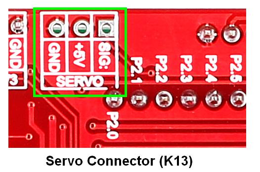
Note: Use adapter for powering since USB doesn’t provide required current
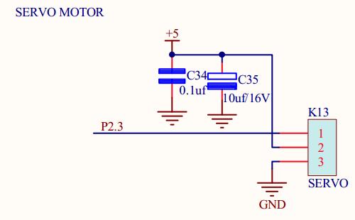
Schematic![]()
Sample Code![]()
|
1 2 3 4 5 6 7 8 9 10 11 12 13 14 15 16 17 18 19 20 21 22 23 24 25 26 27 28 29 30 31 32 33 34 35 36 37 38 39 40 41 42 43 44 45 46 47 48 49 50 51 52 53 54 55 56 57 58 59 60 61 62 63 64 65 66 67 68 69 70 71 |
/************************************************************************* HEADER FILE **************************************************************************/ #include <REGX52.H> #define servo P2_3 /************************************************************************* VARIABLE DECLARATIONS **************************************************************************/ int value=0,i=0; char rec_data; int count=0; /************************************************************************* MAIN FUNCTION **************************************************************************/ void main() { TMOD = 0x21; SCON = 0X50; /* 8-BIT UART, Serial reception enable */ TF1 = 0; /* Clear Timer 1 Overflow Flag */ TR1 = 0; /* Clear TR1 to turn off timer 1 */ TF0 = 0; /* Clear Timer 0 Overflow Flag */ TR0 = 0; /* Clear TR0 to turn off timer 0 */ TH1 = 0XFD; /* Load value to Timer 1 High Byte Register */ TL1 = 0XFD; /* Load value to Timer 1 Low Byte Register */ TH0 = 0xFE; /* Load value to Timer 0 High Byte Register */ TL0 = 0x32; /* Load value to Timer 0 Low Byte Register */ TR1 = 1; /* Set TR1 to turn on timer 1 */ TR0 = 1; /* Set TR0 to turn on timer 0 */ TI = 0; value = 0; while(1) { if(TF0==1) /* Set when timer0 register overflows */ { TF0 = 0; TH0 = 0xFE; /* Load value to Timer 0 High Byte Register */ TL0 = 0x3d; /* Load value to Timer 0 Low Byte Register */ count++; /* Increment count each time the timer overflows */ if(count==value) { servo = 0; } if(count==40) /* When count is 40, time duration = 20ms */ { servo = 1; count = 0; } } if(RI==1) { RI = 0; rec_data = SBUF; if(rec_data=='a') value = 3; /* Load count for 90° when 'a' is received */ if(rec_data=='b') value = 5; /* Load count for 180° when 'b' is received */ if(rec_data=='c') value = 1; /* Load count for 0° when 'c' is received */ } } } /*************************** END OF PROGRAM ****************************/ |
Output![]() The following screenshots explain how to test the sample code.
The following screenshots explain how to test the sample code.
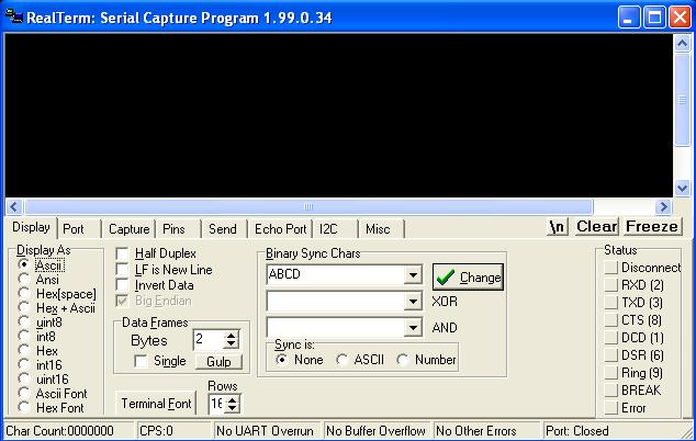
- Step 1: Open Realterm

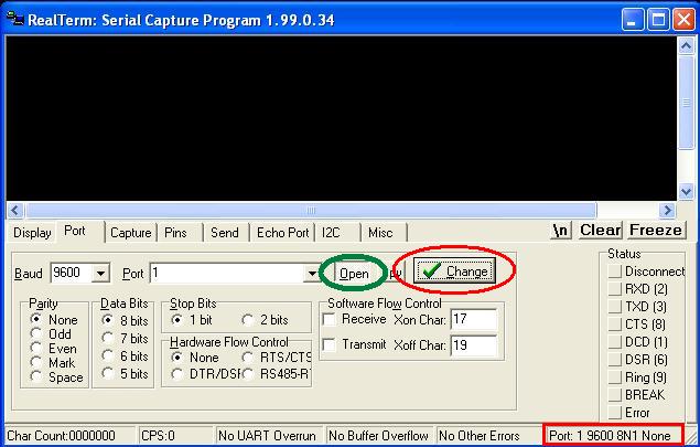
- Step 2: RealTerm opens as shown below
- Step 3: Go to ‘Port’ option, set correct baudrate (which is set as 9600 in the sample code) and correct port
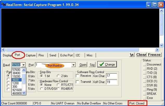
- Step 4: Click ‘Change’ (encircled in red) to apply the changes. Now check the status of Port. If it is closed, click ‘Open’ button (encircled in green) to open it.
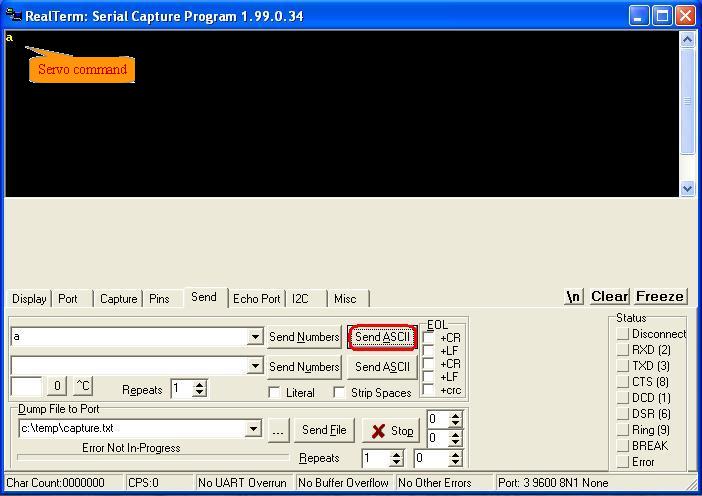
- Step 5: Type the command to transmit in the corresponding data box and then click over Send ASCII as shown below .The transmitted data available in black window , as per this servo turns.
Topics related to AT89S52 Mini Development Board![]()
- AT89S52 Mini Development Board – Overview
- AT89S52 Mini Development Board – LED Interfacing
- AT89S52 Mini Development Board – LCD Interfacing
- AT89S52 Mini Development Board – Serial communication
- AT89S52 Mini Development Board – EEPROM Interfacing
- AT89S52 Mini Development Board – Buzzer Interfacing
- AT89S52 Mini Development Board – Servo Motor Interfacing
- AT89S52 Mini Development Board – Switch Interfacing
- AT89S52 Mini Development Board – RFID Interfacing
Resources![]()
How to buy?![]()
- Click here to buy the rhydoLABZ AT89S52 Mni Development Board (Mini) V1.01
- Click here to buy the rhydoLABZ AT89S52 Development Board
- Click here to buy the rhydoLABZ AT89S52-24PU Microcontroller
- Click here to buy the rhydoLABZ ATMEL 89SXX ISP Programmer (RS232)
- Click here to buy rhydoLABZ Servo motor
Support![]() Please share your ideas with us, visit our forum for discussion
Please share your ideas with us, visit our forum for discussion
Leave a Reply
You must be logged in to post a comment.